3-179
5.2.2 LIFTING UP THE MACHINE IN THE BOOM RAISED POSTURE
• See "Specifications 1.1 Specification List " in the Dimension for the dimensions and mass of
the machine.
• The operator carrying out the lifting operation using a crane must be a properly qualified
crane operator.
• Never raise the machine with any worker on it.
• Use sling instruments for lifting up the machine, including wire ropes or shackles, with
sufficient load intensity for the mass of the machine.
• When lifting, keep the machine horizontal.
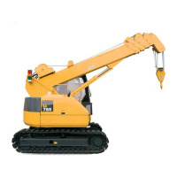
• When carrying out lifting operations, set the lock lever to the LOCK position to prevent the
machine from moving unexpectedly.
• Never go in the area under or around the machine when it is raised.
• The procedure and the scheme for slinging (i.e. put in the holes in two brackets in each left and
right side of the crane frame) other than as specified below must be in no event practiced for
lifting up the machine. If such a practice is un-avoidable, please contact us or our service
agency.
• This practice for lifting up is available both for standard machine configuration and fly-jib
configuration, provided that the fly-jib is stowed in the side of the boom, when equipped.
• Use 2 sling wire ropes and shackles of the same specifications, for lifting up the machine.
• Wire ropes: Breaking load: 78.9 tons or more, dia.37.5mm X 6.9m or better.
• Shackles: Using load: 14.0 tons or more
• When the machine is lifted up in it’s boom raised posture, make sure that the hook block is in
the temporary stowage position. Refer to "Operation 3.7 Machine Traveling Posture" for
details.
When lifting the machine, carry out the operation on firm level ground only as follows.
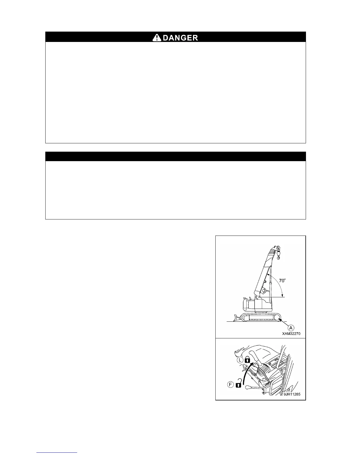
1. Retract the boom to the minimum length, then derrick it up to 70
degrees. Stow the hook block to the temporary position.
2. Swing the upper structure so that the sprocket (A) comes to the
front side of the upper structure.
3. Operate blade control lever to lower the blade.
4. Set the lock lever securely to the LOCK position (L).
5. Stop the engine, and then remove the key from the starter
switch.
6. Close all doors, windows, and covers. Lock covers, caps, and
doors fitted with locks.