6-20
6.2 CHANGING OF FLY-JIB TILT ANGLE
Changing of the Fly-jib tilt angle should be always practiced without any hoisted load and only
with the No.1 Fly-jib. Avoid changing the Fly-jib tilt angle with a hoisted load and/or using No.2
Fly-jib, otherwise excess load is applied to the lever block which may damage it.
• This Fly-jib is adjustable to four tilt angles (0, 20, 40 and 60 degrees) from its stowage position.
Select the suitable position for the intended job.
• The Fly-jib as installed is in its stowage position. In this condition, the signal of the Fly-jib
availability is not transmitted to the moment limiter. To make the Fly-jib operation ready, set
the Fly-jib to one of the four Fly-jib operation angles (0, 20, 40 and 60 degrees).
• When the Fly-jib tilt angle is set to other than its stowage position, the tilt angle data is
transmitted to the moment limiter, then the moment limiter display indicates the angle, as well
as computing the rated total load automatically.
6.2.1 CHANGING OF FLY-JIB TILT ANGLE
To change the tilt angle of the Fly-jib from its stowage position, follow the instructions below:
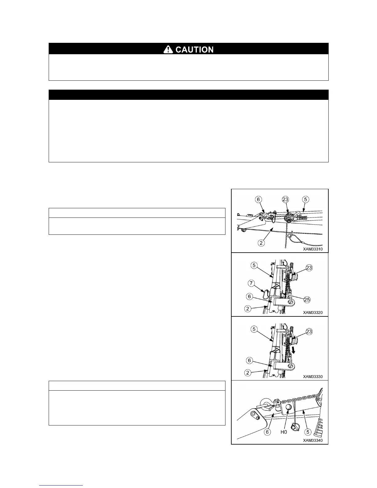
1. Set the attached lever block (23) between the tilt angle adjuster
outer rod (5) and inner rod (6).
Lever block (23) handling will be easier, when you set the lever
side to the outer rod side (5).
2. Detach the linchpin (25) from the position pin (7), then use the
lever block (23) and extract the position pin (7).
3. Wind up the lever block (23) to provide some slack between
outer rod (5) and inner rod (6), and then lower the No.1 Fly-jib
(2).
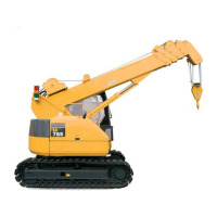
When the No.1 Fly-jib (2) lowers, the inner rod (6) lowers
together. Use the lever block (23) further to match the hole (H0)
of the inner rod (6) for 0 degree angled Fly-jib and the hole of the
outer rod (5).