6-19
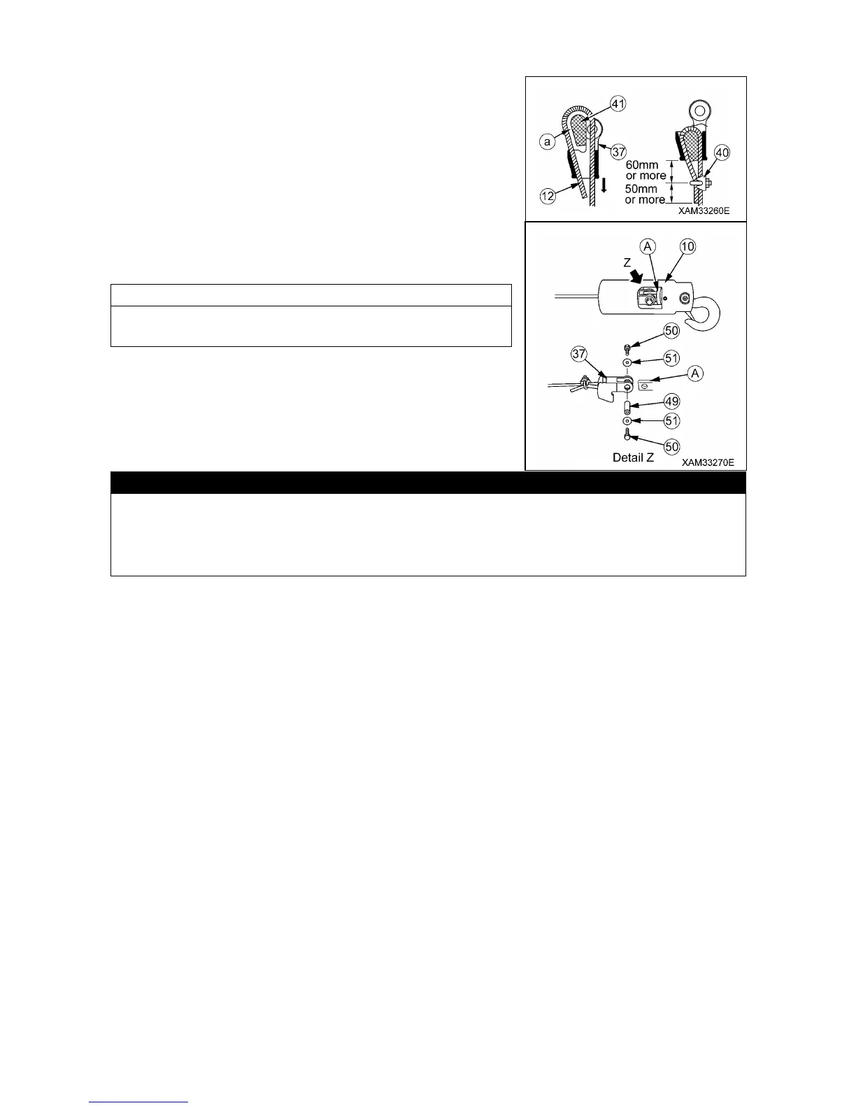
19. Put the wire rope (12) through the wire socket (37), as removed
in 13 above, and set the rope wedge (41) to position (a). Pull the
wire rope (12) intensely to the direction of the arrow.
20. Install the rope clip (40) to the wire rope (12). Refer to the
Figure on the right for the rope clip position.
21. Insert the wire socket (37) into connection base (A) inside the
hook (10). Adjust the holes of both and insert a pin (49), then
secure it with end plates (51) and bolts (50).
The hook (10), pin (49), bolts (50) and end plates (51) are
specific Fly-jib parts and packaged separately.
The Fly-jib as installed is still in the stowage position. In this condition, the signal of the Fly-jib
availability is not transmitted to the moment limiter. To make the Fly-jib operation ready, set the
Fly-jib to one of the four Fly-jib operation angles (0, 20, 40 and 60 degrees).
Refer to "Fly-jib 5.2 Changing of the Fly-jib Tilt Angle" for details.