IMPULSE•VG+ Series 3 Instruction Manual – 07/25/05
5-51
S-Curve Acceleration/Deceleration
A S-Curve pattern is used to reduce shock and provide smooth transitions during machine
acceleration and deceleration. S-Curve characteristic time is the time from the output frequency to
the set accel/decel time. See S-Curve Characteristic timing diagrams below and on the following
page.
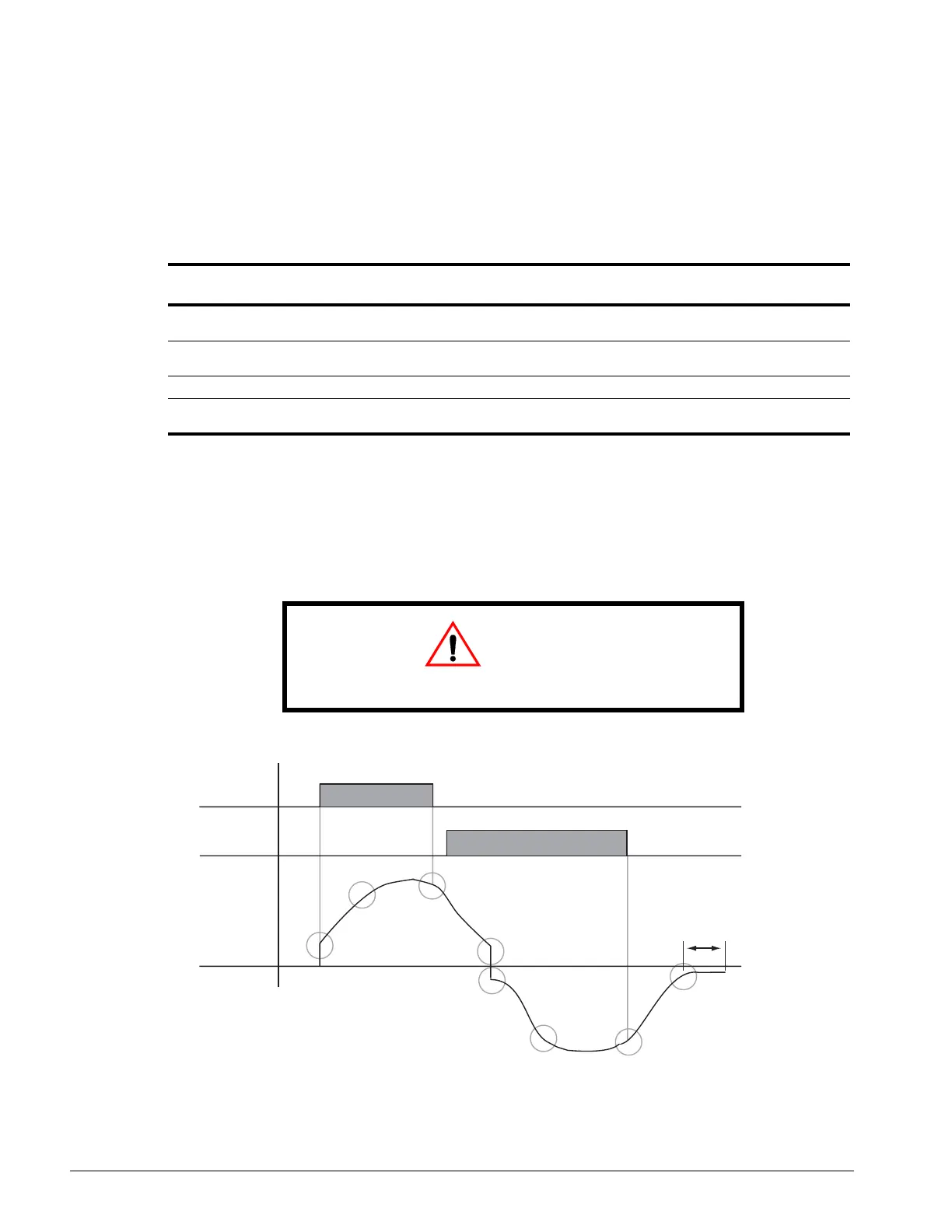
The figure below shows FWD/REV run switching during deceleration to stop. The S-curve function
will add time to the acceleration and deceleration. Time to accelerate from the minimum frequency
to the maximum frequency (total acceleration) = B5-01 + (D9-01 + D9-02)/2.
Figure 5-30: S-Curve Characteristics–FWD/REV Operation
Parameter
Code Display Function Range Initial Value
Access
Level
D9-01* S-Crv Acc @ Start Sets S-Curve time at Accel
start
0.00–2.50 sec − Adv
D9-02* S-Crv Acc @ End Sets S-Curve time at Accel
end
0.00-2.50 sec − Adv
D9-03* S-Crv Dec @ Start Sets S-Curve time Decel start 0.00–2.50 sec − Adv
D9-04 S-Crv Dec @ End Sets S-Curve time at Decel
end
0.00–2.50 sec 0.20 Adv
*Initial value is determined by X-Press Programming (Table 4.1 to 4.2).
CAUTION
CAUTION Accel/Decel times will be extended.
requency
utput
un(FWD)
ommand
un(REV)
ommand
D9-01
D9-02
D9-03
D9-04
D9-01
D9-02
D9-03
D9-04
DC Injection Brakin
Time at Stop
D1-04

 Loading...


