IMPULSE•VG+ Series 3 Instruction Manual – 07/25/05
5-7
Stop Method
B3-03 selects the stopping method suitable for the particular application.
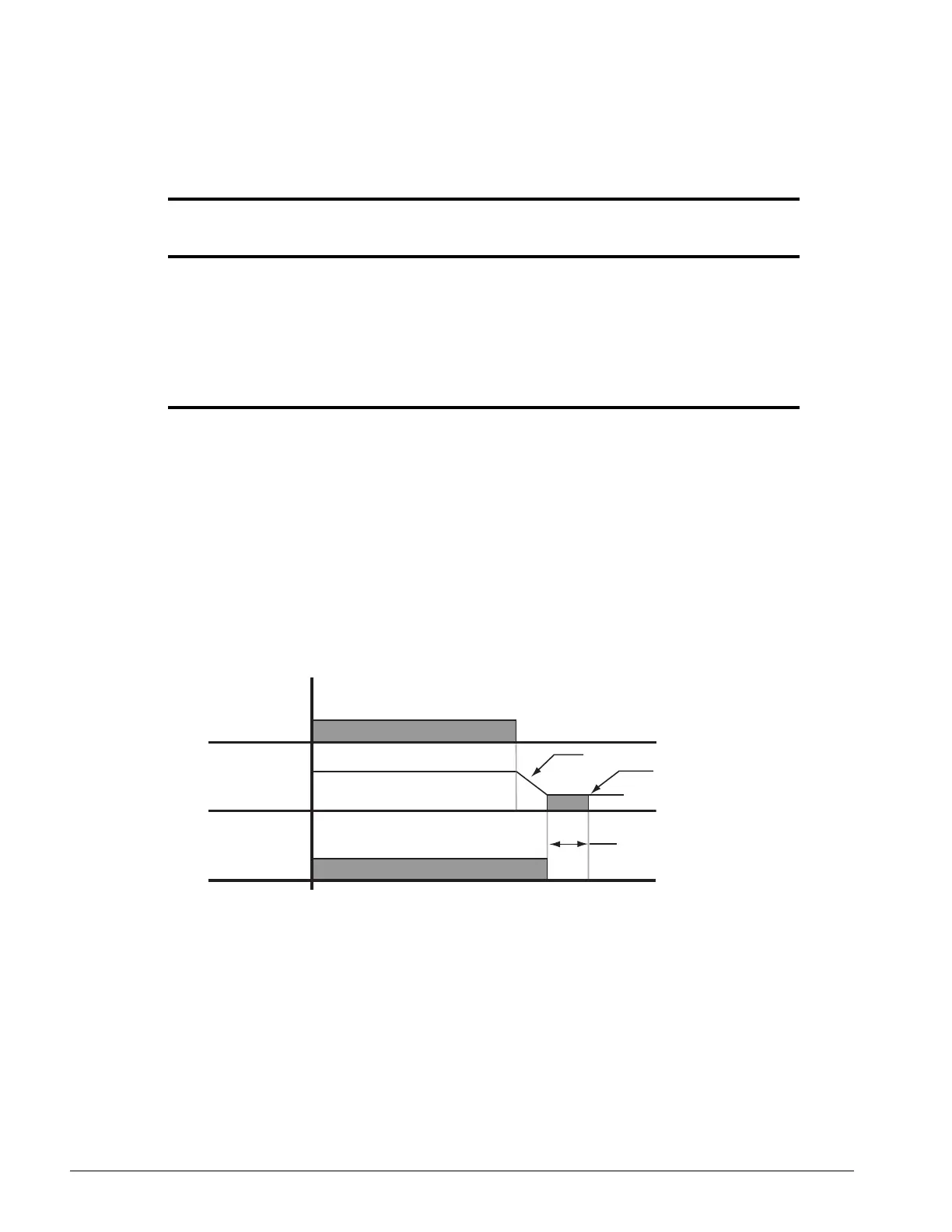
Decel to Stop (B3-03=0)
Upon removal of the FWD or REV run command, the motor decelerates at a rate determined by the
time set in deceleration time 1 (B5-02) and DC injection braking is applied after the DC injection
start frequency D1-01 has been reached. If the deceleration time is set too short or the load inertia is
large, an overvoltage fault (OV) may occur during deceleration. In this case, increase the
deceleration time or install an optional braking transistor and/or braking resistor.
Braking torque: without braking resistor, approximately 20% of motor rated torque; with braking
option, approximately 150% of motor rated torque.
Figure 5-2: Decel to Stop
Paramet
er Code Display Function Range Initial Value
Access
Level
B3-03 Stop Method Determines stop method. * Adv
0 Decel to Stop
(A1-03=0)
(Fig 5-2)
1 Coast to Stop
(A1-03=1)
(Fig 5-3)
4 Decel with timer
(Traverse mode only)
Fig (5-4)
6 No Load Brake (A1-03=2) (See No-Load Brake Start/Stop)
* Initial value is determined by X-Press Programming (Table 4.1-4.2)
Run
Command
Frequency
Output
Brake
Output
Decel Time (B5-02)
Zero speed level (Frequency at DC
injection braking start D1-01)
DC Injection Brake time
at stop (D1-04)

 Loading...


