IMPULSE•VG+ Series 3 Instruction Manual – 07/25/05
5-23
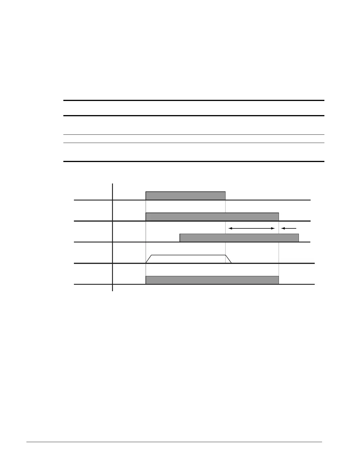
Load Float Time 2
When Load Float (C8-10) is enabled, it maintains the motor shaft at a stationary position. Load Float
Time 2 is enabled by a MFI (Multi-Function Input) that is programmed as the digital input data 35
(H1-01~06=35). If load float is being used, this time (C4-01) will be added to the standard load float
time (C8-10).
Figure 5-16: Load Float
Parameter
Code Display Function Range Initial Value
Access
Level
C4-01 Load Float Time 2 Maximum duration of Zero
Servo action at multi-function
input. Data = 35
0–255 sec 10 Adv
C4-02 Load Float Gain Zero Servo multiplier. 0–100 * Adv
C4-03 Load Float Count Zero Servo completion width.
Enables Multi Function output
= 25
0–16383 10 Adv
* 10/20 depending on drive size
Run
Command
Brake
Output
Internal
Run (IBB)
Zero Servo
MFI=3A
Nfb
C4-01

 Loading...


