IMPULSE•VG+ Series 3 Instruction Manual - 07/25/05
3-12
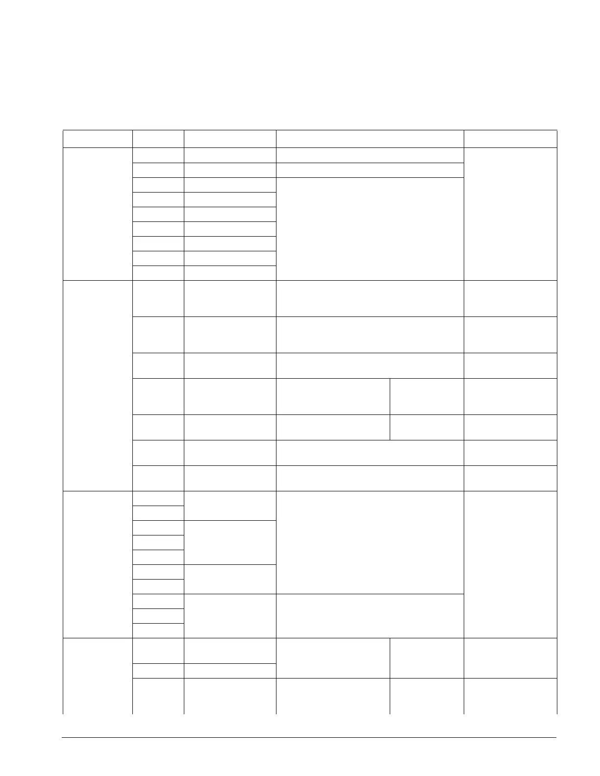
Control Circuit Terminals
The table below outlines the functions of the control circuit terminals.
Classification Terminal Signal Function Description Signal Level
Sequence
Input Signal
S1 Forward run/stop Forward run when closed, stop when open 120 VAC ± 10%
S2 Reverse run/stop Reverse run when closed, stop when open
S3 Speed 2
Multi-function contact inputs (H1-01 to H1-06)
S4 Speed 3
S5 Speed 4
S6 Speed 5
S7 External Fault
S8 M-Speed Gain 1
SN Control Input Common
Analog
Input Signal
+V +15V
Power supply output
For analog command +15V power supply +15V
(Allowable current 20
mA max.)
-V -15V
Power supply output
For analog command -15V power supply -15V
(Allowable current 20
mA max.)
A1 Master frequency
reference
-10 to +10V/-100% to 100%
0 to +10V/0 to 100%
-10 to +10V (20k Ohm),
0 to +10V/(20k Ohm)
A2 Multi-function analog
reference
4 to 20 mA/0 to 100%
-10 to +10V/-100% to 100%
0 to 10 V/0 to 100%
Multi-function
analog reference
(H3-09)
4 to 20mA (250 Ohm)
-10 to +10V (20k Ohm),
0 to +10V/(20k Ohm)
A3 Multi-function analog
input
-10 to +10V/-100% to +100%
0 to +10 V/0 to 100%
Auxiliary analog
input (H3-05)
-10 to +10V (20k Ohm),
0 to +10V/(20k Ohm)
AC Common terminal for
control circuit
0V –
E(G) Connection to shield
sheath of signal lead
––
Relay
Output Signal
M0
Brake output
N.O. Contact
Multi-function output (H2-01 to H2-03)
Dry contact
Contact capacity:
250VAC, 1A or less
30VDC, 1A or less
M1
M2 N.O./N.C. Contact
M3
M4
M5
Fault annunciate
M6
MA Fault contact output
(NO/NC contact)
Terminals MA & MC N/O; closed at major faults
Terminals MB & MC N/C open at major fault
MB
MC
Analog
Output Signal
FM Multi-Function Analog
Output 1
0 to ± 10V Multi-function
analog monitor
(H4-01 to H4-03)
0 to ±10V Max. ±5%
2mA or less
AC Common
AM Multi-Function Analog
Output 2
0 to ± 10V Multi-function
analog monitor 2
(H4-04 to H4-06)
0 to ±10V Max. ±5%
2mA or less
 Loading...