IMPULSE•VG+ Series 3 Instruction Manual - 07/25/05
3-11
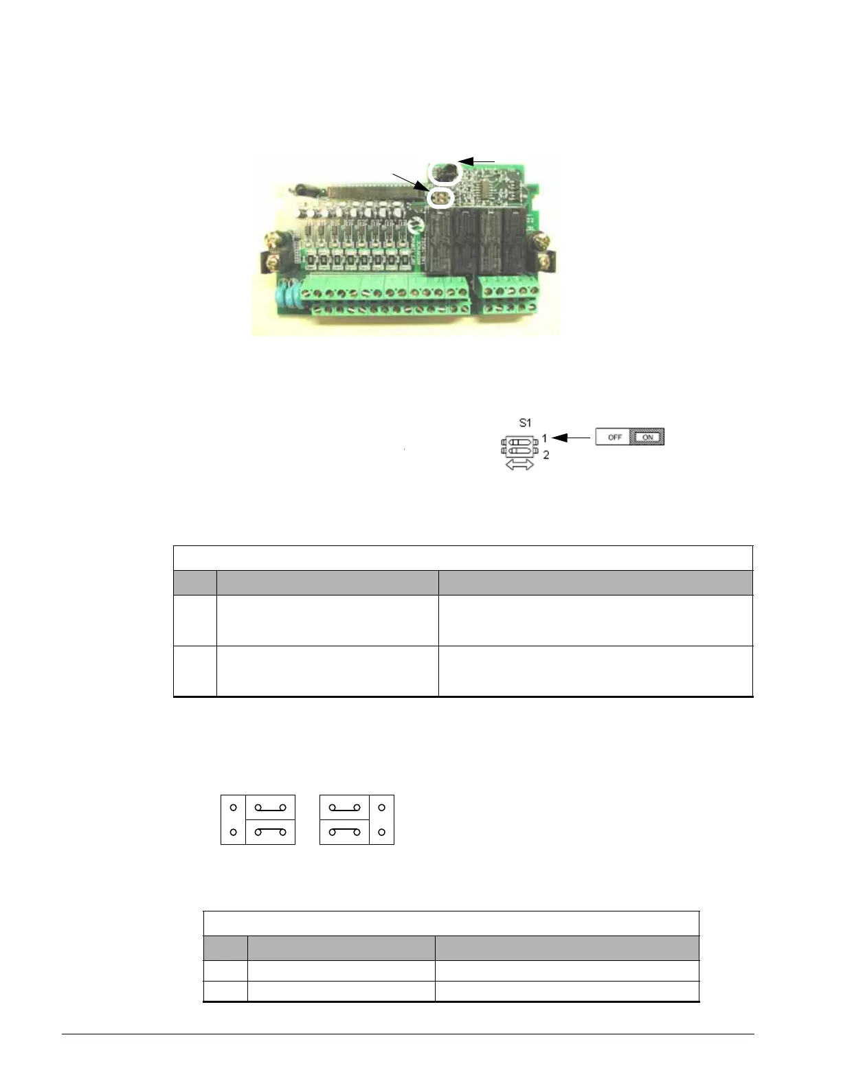
Control Circuit board 2PCB
DIP Switch S1 and Jumper CN15
Figure 3-4: DIP Switch S1 and Jumper CN15 Location
Dip Switch S1
DIP Switch S1 is described in this
section. The functions of DIP switch S1
are shown in the table below.
Figure 3-5: DIP Switch S1 Function
Jumper CN15
Jumper CN15 is described in this section. The jumper
position of CH1 and CH2 determines the signal level of
the multi-function analog output FM and AM,
respectively. The functions and positions of CN15 are
shown in the table below.
CN5
S1
DIP Switch S1
Name Function Setting
S1-1 RS-485 and RS-422 terminating resistance OFF: No terminating resistance
ON: Terminating resistance of 110 Ohm
Factory Default = OFF
S1-2 Input method for analog input A2 OFF: 0 to 10Vdc or -10 to 10Vdc (internal resistance: 20K)
ON: 4-20mA (internal resistance: 250 Ohm)
Factory Default = OFF
Jumper CN15
Name Multi-function Analog Output Output Range
CH1 FM V: 0 to 10V or -10V to +10V (default)I: 4 to 20mA
CH2 AM V: 0 to 10V or -10V to +10V (default)I: 4 to 20mA
CH1
CH2
CN15
VI
Control Circuit Terminals - Continued

 Loading...


