IMPULSE•VG+ Series 3 Instruction Manual - 07/25/05
3-8
Power Circuit Wiring Procedures
To wire the power circuit for IMPULSE•VG+ Series 3:
1. Run the three-phase power supply wires through an appropriate enclosure hole.
2. Referring to “Suggested Circuit Protection Specifications—IMPULSE•VG+ Series 3” and the
following two tables, connect the three-phase power supply wires to a circuit protection system.
3. Connect the three-phase power supply wires from the circuit protection Terminals L1, L2 and
L3.
4. From Terminals T1, T2 and T3, connect the power output wires to the motor. If a load reactor is
used, connect these output wires to the reactor input instead; then connect the reactor output to
the motor.
NOTE: If a device that can interrupt power is installed between the drive and the motor,
install a reactor on the output side of the drive.
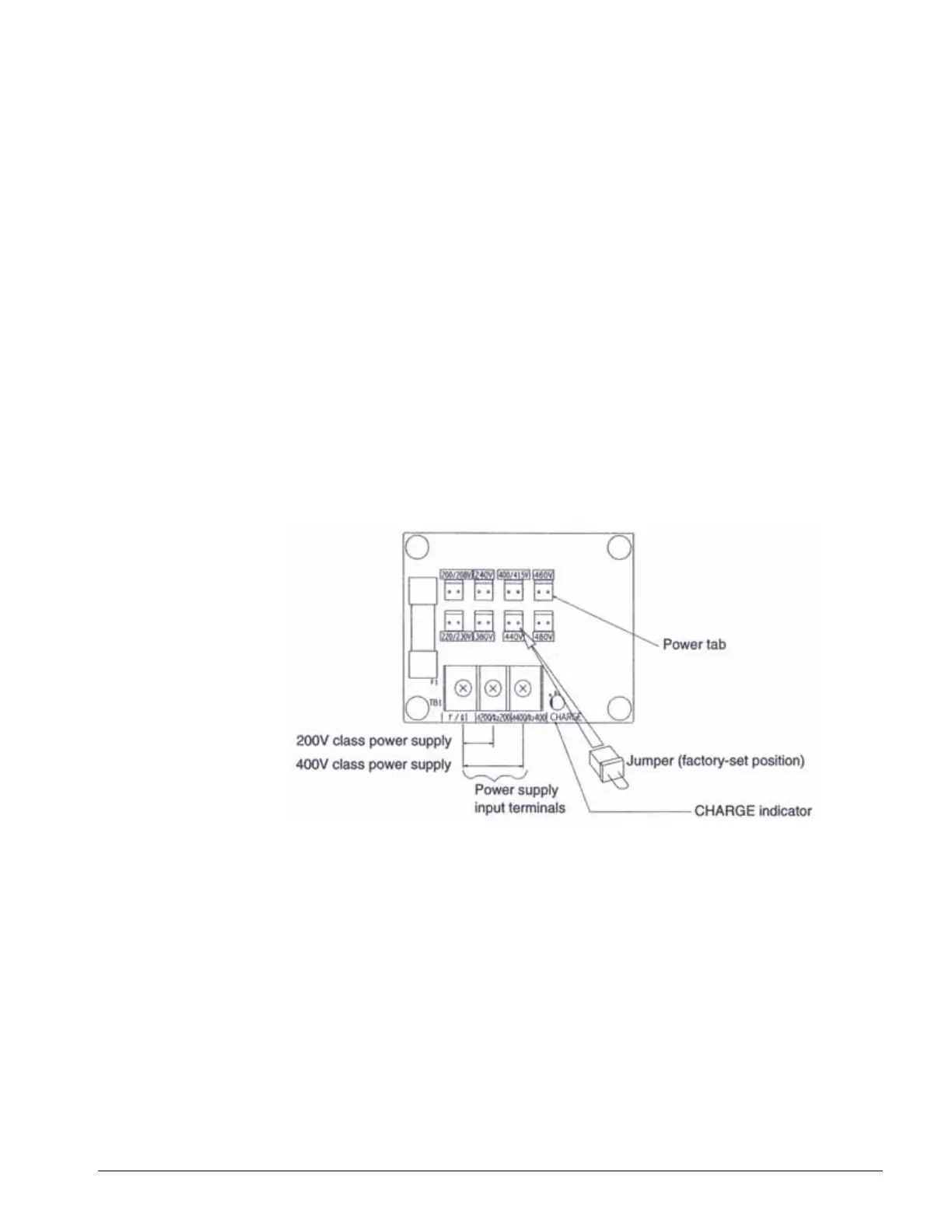
5. For Models 4150-FVG+S3 and greater, ensure the jumper plug is inserted in the printed-circuit
board (8PCB), which is underneath the control board, as follows:
Figure 3-2: Models 4150-FVG+S3 to 4590-FVG+S3

 Loading...


