IMPULSE•VG+ Series 3 Instruction Manual – 07/25/05
5-52
Motor Parameters
• E1 V/f Pattern 1
• E2 Motor Set-up
• E3 Motor 2 Method
• E4 Motor 2 V/f Pattern
• E5 Motor 2 Set-up
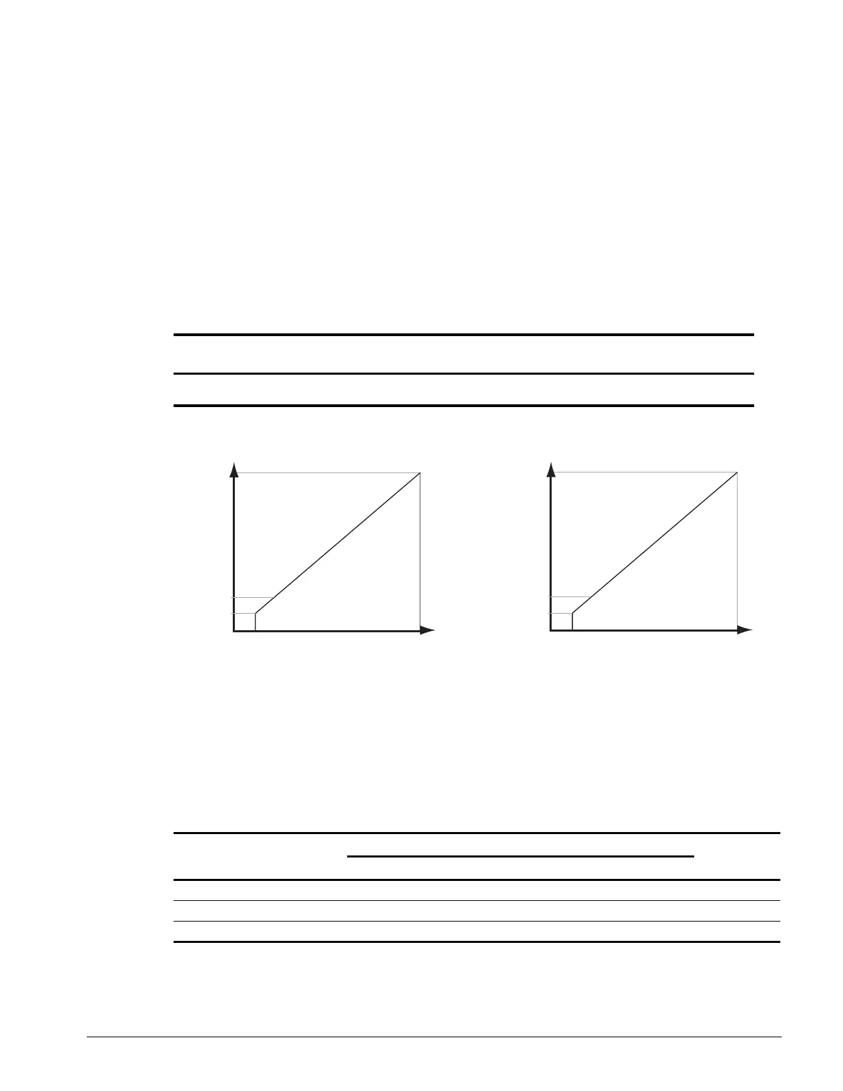
Voltage/Frequency Pattern
Figure 5-31: E1-01 Input Voltage
• When using flux vector control mode, the V/f pattern voltage values will be adjusted
by the Auto-Tuning function.
• Factory setting is 230 (230V units) or 460 (460V units).
The setting E1-01 adjusts the overvoltage level, braking transistor turn on level and the stall
prevention level during deceleration.
Parameter
Code Display Function Range
Initial
(1)
Value
Access
Level
E1-01 Input Voltage Sets input voltage 155-255/
310-510
230/460 Adv
Table 5-5:
Inverter
Voltage
E1-01
Setting
Overvoltage Trip Braking Transistor
Stall LevelTrip Reset On Off
230 150-255 400V 380V 380V 375V 380V
460 ≥400 800V 760V 760V 750V 760V
460 <400 720V 680V 660V 650V 670V
Parameter E1-01 performs the above mentioned function in all three control modes.
10.4V E1-10
15.6V E1-08
208V E1-05
(V)
(Hz)
E1-01=208
11.5V E1-10
17.2V E1-08
230V E1-05
(V)
(Hz)
E1-01=230

 Loading...