IMPULSE•VG+ Series 3 Instruction Manual - 07/25/05
3-13
Pulse I/O Signal
RP Pulse Input Pulse input frequency
reference
Function set by
H6-01
0 to 32kHz (3k) +5%
High level voltages
3.5 to 13.2
Low level voltages
0.0 to 0.8
Duty Cycle (on/off)
30% to 70%
MP Pulse Monitor Pulse output frequency Function set by
H6-06
0 to 32kHZ
+
5% output
(load: 1.5k)
RS-485/422
R+
Modbus
communication input
For 2-wire RS-485, jumper R+ and S+ and jumper
R- and S-
Differntial input,
PHC isolation
R-
S+
Modbus
communication output
Differntial output,
PHC isolation
S-
IG Signal Common
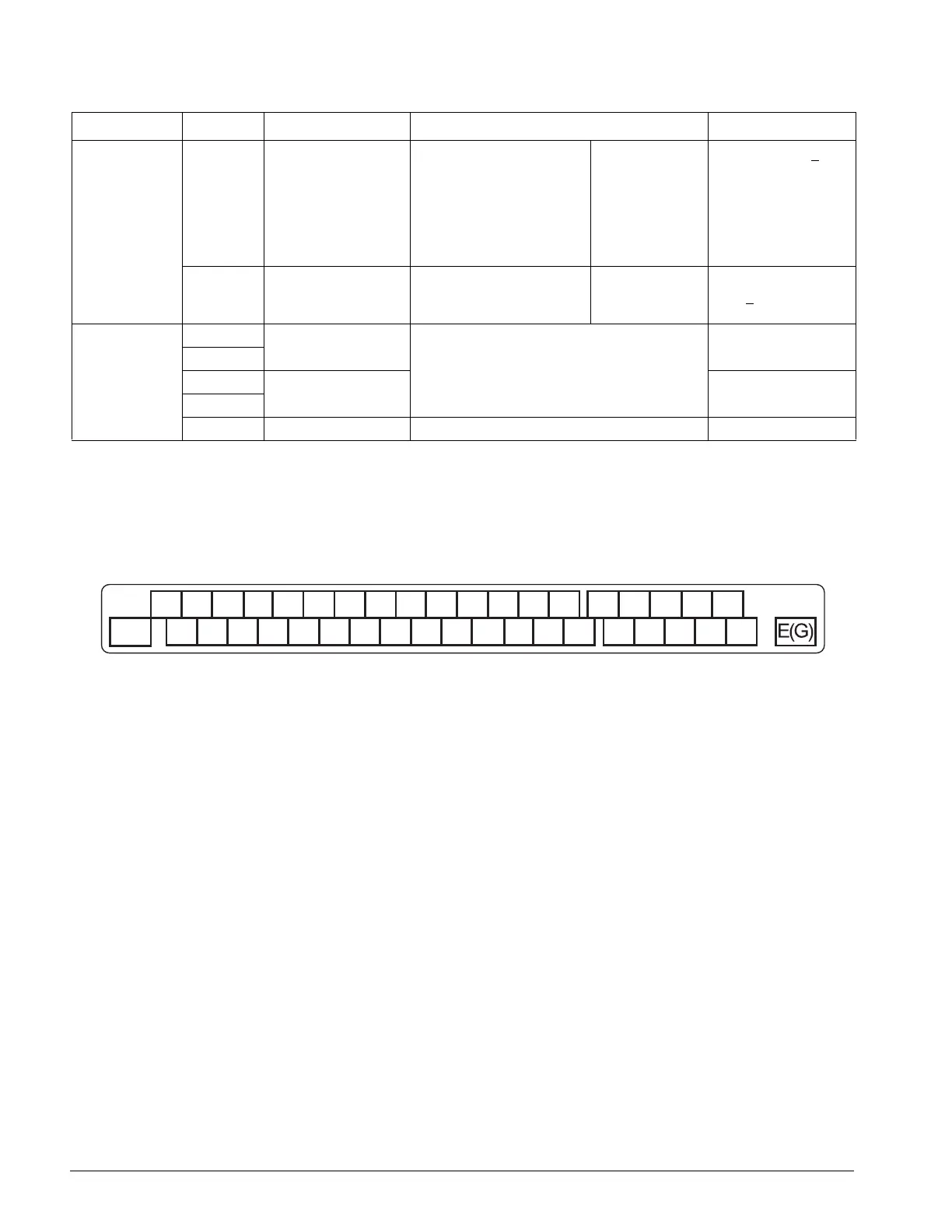
Classification Terminal Signal Function Description Signal Level
Control Circuit Terminal Diagram
FM
AC
AM
A3 +V
AC
-V
144-42098
X2
X2 X2 S1 S2
S3 S4 S5
S6 S7
S8
M2
M4
M0
M1
A1 A2 MP AC RP R+ R- M5 M6
MAMB
MC
M3S-S+IGE(G)

 Loading...


