M&M
R
EFRIGERATION
I
NC
. A-3
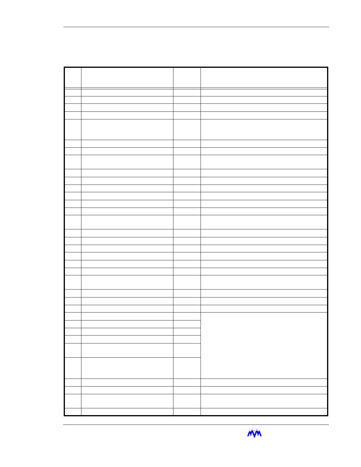
Appendix A: Discrete Alarms
Discrete Alarms
No. Parameter Name Level Comments
1.
Memory Initialized Alarm
2.
Frame Overrun Alarm
3.
Timer Allocation Fail
4.
RAM Size Failure Low Fail Indicates a hardware problem with the RAM Chip.
5.
Power Low Reset Fail The Power has drooped below a threshold but did
not completely go away. A sensor or other device
may be shorted
6.
Power Fail Reset Fail Power was lost
7.
Pushbutton Reset Fail The reset button on Main Board was pressed.
8.
Watchdog Reset Fail The Software was unable to complete it’s cycle.
May be communications or interrupt related.
9.
Operator Reset Fail Reset from a screen save from the keypad or PC
10.
Auxiliary Contact 1 Fail Open to Fail
11.
Auxiliary Contact 2 Fail Open to Fail (Not available with Economizer Option)
12.
Suction Pressure Sensor Bad SNSR
13.
Discharge Pressure Sensor Bad SNSR
14.
Oil Press After Filter Sensor Bad SNSR
15.
Oil Press Before Filter Sensor Bad SNSR Oil pressure below filter sensor bad (all others)
Oil pressure above discharge sensor bad (STAL)
16.
Discharge Temperature Sensor Bad SNSR
17.
Oil Temperature Sensor Bad SNSR
18.
Oil Sump Temperature Sensor Bad SNSR
19.
Suction Temperature Sensor Bad SNSR
20.
Motor Current Sensor Bad SNSR
21.
Slide Valve Sensor Bad SNSR
22.
Process Temperature Sensor Bad
(Option)
SNSR
23.
Starting Oil Pressure Low OEM
24.
Starting Slide Valve Position High OEM
25.
Stopping Slide Valve Position High OEM
26.
Motor Off/Current Normal/Aux Open Fail The Micro checks state of Motor Output, Aux Input,
and Motor Current to verify correct operation. Motor
Current above 10% of entered CT size or Aux con-
tact closed indicates the motor is running.
If Motor is running when it should be off, the Micro
will take the following steps: (1) Failure signal is
generated to alert operator; (2) Oil pump is started, if
one exists; (3) Slide valve is forced to continuous
unload, and; (4) Liquid injection controls on oil tem-
perature
27.
Motor On/Current Low/Aux Open Fail
28.
Motor On/Current Normal/Aux Open Fail
29.
Motor Off/Current Low/Aux Closed Fail
30.
Motor Off/Current Normal/Aux
Closed
Fail
31.
Motor On/Current Low/Aux Closed Fail
32.
Economizer Shutdown (Option) Fail Replaces Aux 2 Shutdown
33.
Master Shutdown Fail The master has requested a shutdown
34.
ECP Shutdown Fail A shutdown was requested using the ECP or Mod-
bus protocol
35.
DF1 Shutdown Fail A shutdown was requested using the DF1 Protocol
 Loading...