M&M
R
EFRIGERATION
I
NC
. 3-25
Chapter 3: Operational Procedures
Alarm & Failure Area
The right most highlighted status banner section displays the Alarm and Failure
Status of the system. When a new alarm or failure occurs, this area will flash from
highlighted to non-highlighted to inform the operator. The area will stop flashing
but remain highlighted when the operator has used the CLEAR key to acknowl-
edge the alarm or failure. Once all alarm and failure conditions have be corrected
the operator may again press the CLEAR key to clear the alarm from the display.
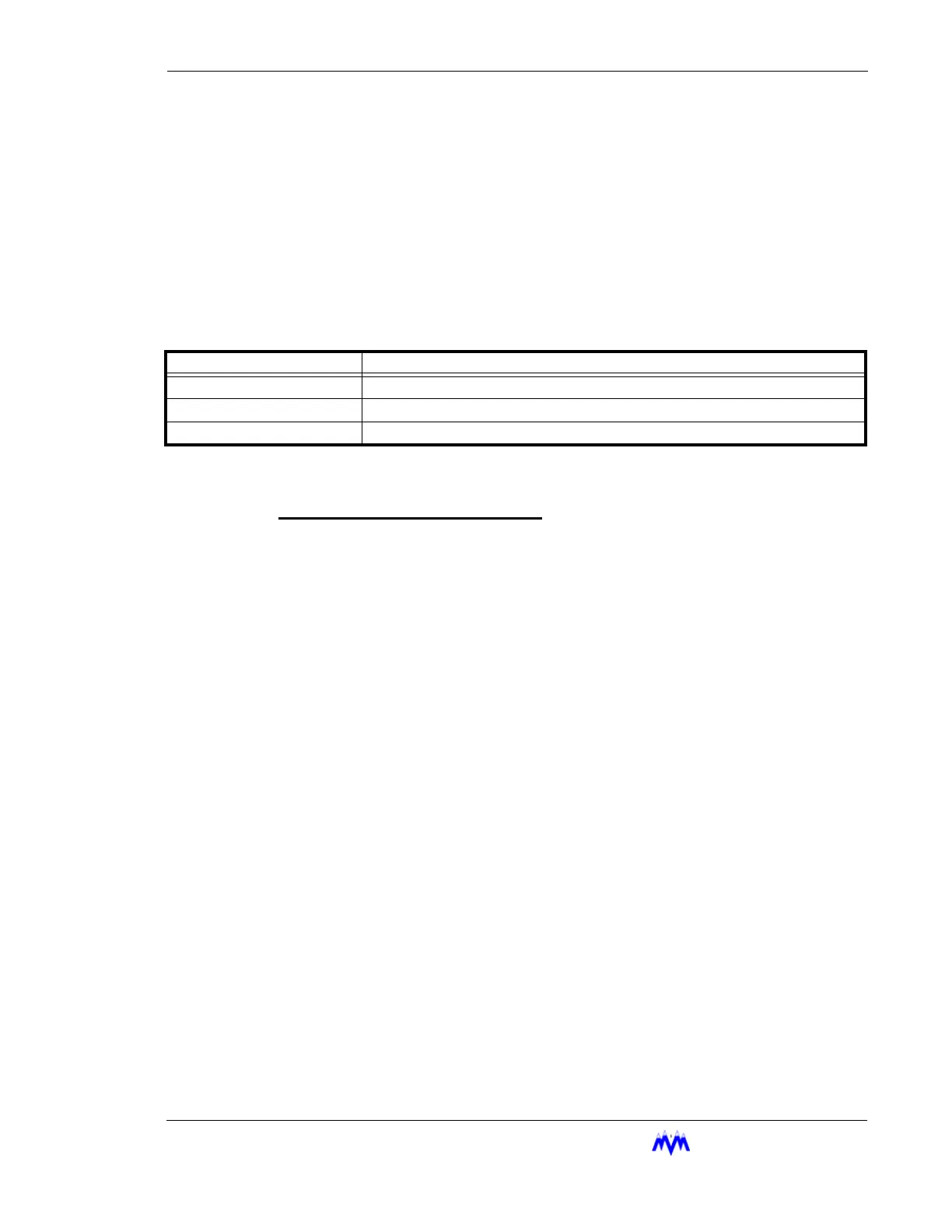
The following table lists the various alarm/failure states and their meanings.
NOTE: If both an alarm and failure exist the failure state will be displayed as it has a higher priority.
Alarm Status
Compressor Graphics Screen
The Compressor Graphics screen shows all of the same information as the Compres-
sor Status screen, but in a graphical format. Animation of the compressor and oil
pump are used whenever the compressor is running so that the user may quickly
evaluate the condition of the compressor.
ALARM MESSAGE SYSTEMS STATUS
NORM No alarm or failure is active, the screw is operating normally.
ALARM An alarm is active on the screw.
FAIL A failure is active on the screw.
 Loading...