M&M
R
EFRIGERATION
I
NC
. 3-23
Chapter 3: Operational Procedures
Manual control of the slide valve is discussed in the Capacity Control section and
alarms and failures are discussed in the Alarm/Failure section of this manual.
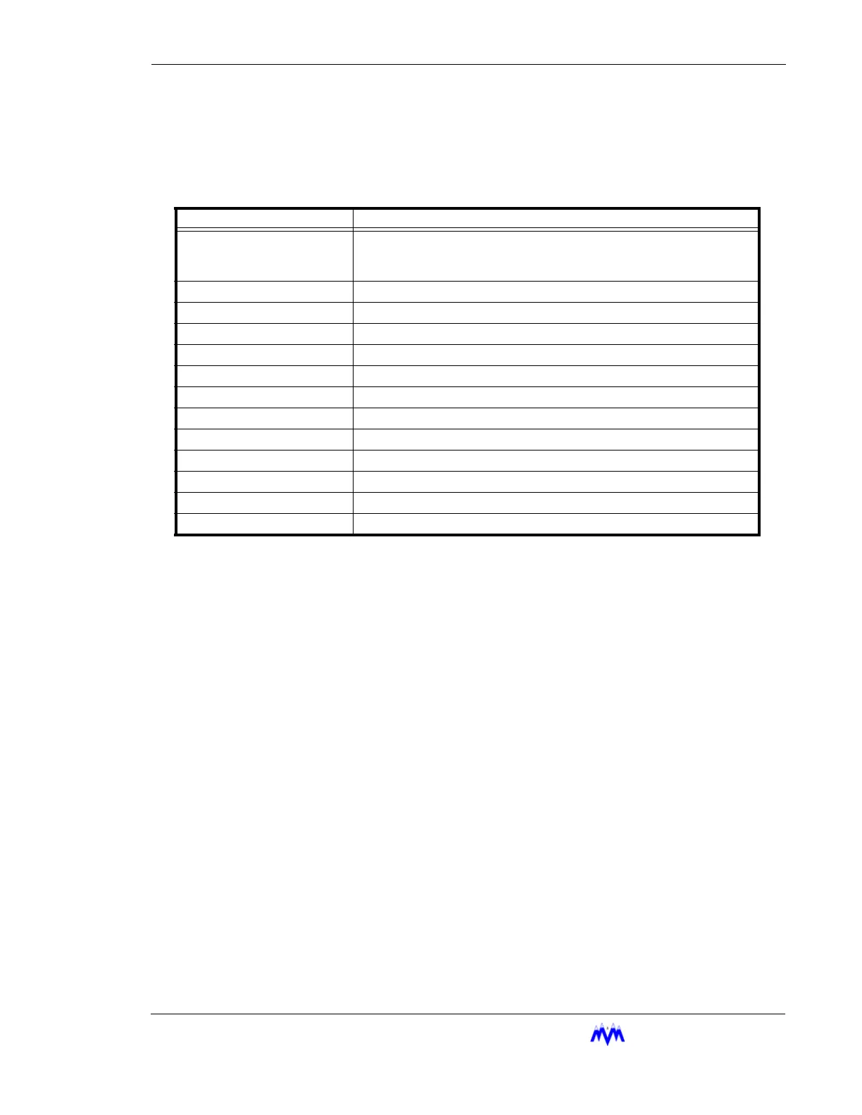
The following table lists the various parameters displayed on the screw status screen.
NOTE: The Oil Pressure and Oil Filter Pressure values are computed values based on various raw
sensor values, depending on the compressor.
Status Banner
The Status Banner is located at the bottom of the Compressor Status screen,
Compressor Graphics screen, Active Alarms & Failures screen, and Auto-Start
Warning status screen. The Banner consists of three highlighted sections which
provide the user with the status of the following system conditions.
• Current System State
• Current Operating mode
• Alarm & Failure Status
PARAMETER DESCRIPTION
S1-S4, P1-P4, SY
The active capacity control setpoint. S1-S1 indicate represent Suc-
tion Pressure setpoints, P1-P4 represent Process Temperature set-
points, and SY represents the Sequenced setpoint.
SP Suction Pressure
DP Discharge Pressure
OP Oil Pressure
OF Oil Filter Differential Pressure
SV Slide Valve Position (Adjusted based on Vi Position)
MA Motor Current
ST Suction Temperature
DT Discharge Temperature
OT Oil Temperature
OS Oil Sump Temperature
PT Process Temperature (Option)
Vi Vi Position
 Loading...