Standard Screw Compressor - RWB Series
C-2
M&M
R
EFRIGERATION
I
NC
.
Hardware Interface Description
Hardware Requirements
The M&M Screw compressor uses the on-board COMM 1 port for Modbus communica-
tions and PORT 2 on the optional Communications Expansion board for DF1 communica-
tions. The hardware configuration for both protocols is 5-volt RS-422.
Interface Connections
Physical interface connections for Modbus communications are made at COMM 1 located
on the right side of the lower edge of the main microprocessor board next to the battery.
The interface connection for DF1 communications are made at PORT 2 on the optional
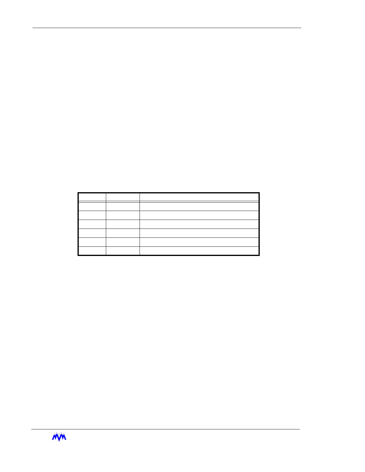
Communications Expansion board. The following table shows the pin-outs for the M&M
hardware for both COMM 1 and PORT 2.
The use of low capacitance twisted/shielded cable is required (e.g. Belden #9503 or eq.).
The shields should be grounded at the master computer end of the cable and floated at
the microprocessor end.
Figure 1 shows the interface cabling connections for typical Modbus applications. Also
shown are the recommended shield grounding requirements for an in-line data path and a
split data path. Other controllers or PC configurations may be different.
NOTE: Since Modbus communications share a port with M&M communications, Dip switch SW3
Position 7 on the main board must be set to the ON position to enable the Modbus commu-
nications protocol.
DF1 communications, the M&M controller must be outfitted with the optional Communica-
tions Expansion board. The board must be configured with external serial port 2 enabled.
Figure 2 shows a typical connection for an Allen-Bradley PLC-5 using an RS-232C/RS-
422 adapter to multiple M&M compressors. The Allen-Bradley programmable controller
must be configured for RS-422 multi-drop communications.
NOTE: The AB PLC-5/60 Comm port 0 may be configured as RS-422 multi-drop. However, the
implementation is non-standard and is limited as to the communications speed and wire
length. The signal levels are also inverted from normal RS422. The use of an external
RS232-to-RS422 converter is recommended to allow standard high-speed long-distance
communications.
Pin Name Function
1 TX+ Transmit Data (Positive)
2 TX- Transmit Data (Negative)
3 GND Ground
4 GND Ground
5 RX- Receive Data (Negative)
6 RX+ Receive Data (Positive)