M&M
R
EFRIGERATION
I
NC
. C-3
Appendix C: Hardware Interface Description
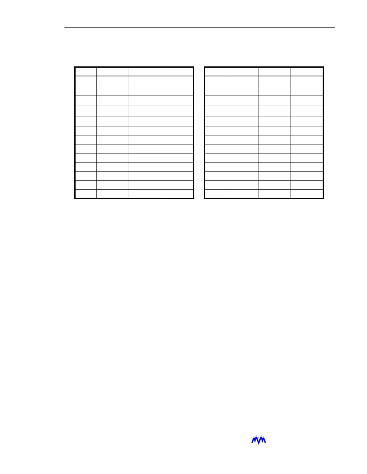
The following pin-outs apply to the Comm 0 port of the PLC/5-60 programmable controller.
Pin RS-232C RS-422A RS-423 Pin RS-232C RS-422A RS-423
1 C.GND C.GND C.GND 14 NOT USED TXD.OUT SEND COM
2TXD.OUT
TXD.OUT
+
TXD.OUT 15
3RXD.IN
RXD.IN
+
RXD.OUT 16 NOT USED RXD.IN REC COM
4RTS.OUT
RTS.OUT
+
RTS.OUT 17
5CTS.IN
CTS.IN
+
CTS.IN 18
6 DSR.IN DSR.IN DSR.IN 19 NOT USED RTS.OUT NOT USED
7 SIG.GND SIG.GND SIG.GND 20 DTR.OUT DTR.OUT DTR.OUT
8 DCD.IN DCD.IN DCD.IN 21
9 22 NOT USED DSR.IN NOT USED
10 NOT USED DCD.IN NOT USED 23 NOT USED DTR.OUT NOT USED
11 24
12 25
13 NOT USED CTS.IN NOT USED