Manitowoc Published 05-03-17, Control # 228-03 3-11
16000 SERVICE/MAINTENANCE MANUAL ELECTRIC SYSTEM
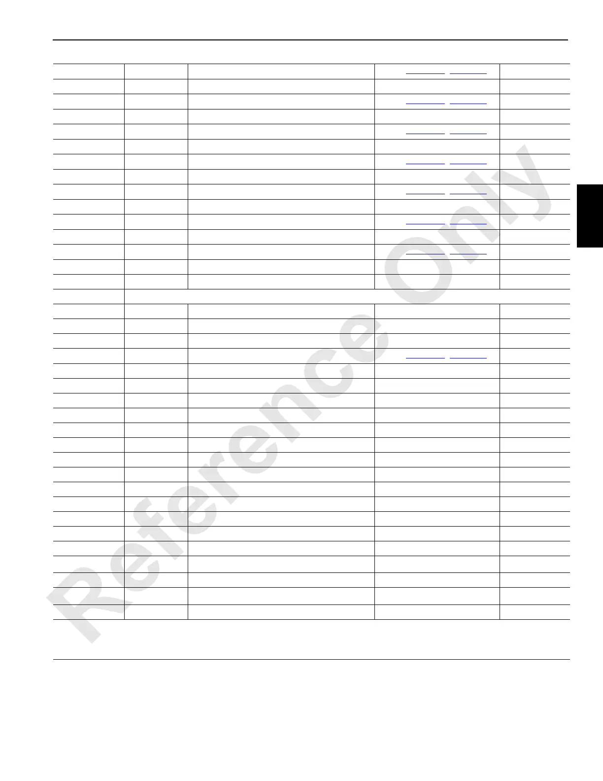
W34-S DO-18 Pump 6 Control (Drum 2/Drum 1)
See
Table 3-2, page 3-6
CAN25-3-2
W34-T Ground Pump 2 Control (Left Travel/Drum 3) Ground N/A
W34-U DO-19 Pump 2 Control (Left Travel/Drum 3)
See
Table 3-2, page 3-6
CAN25-3-4
W34-V Ground Pump 2 Control (Left Travel/Drum 3) Ground N/A
W34-W DO-20 Pump 2 Control (Left Travel/Drum 3)
See
Table 3-2, page 3-6
CAN25-3-8
W34-X Ground Pump 1 Control (Right Travel/Drum 4) Ground N/A
W34-Z DO-21 Pump 1 Control (Right Travel/Drum 4)
See
Table 3-2, page 3-6
CAN25-3-16
W34-a Ground Pump 1 Control (Right Travel/Drum 4) Ground N/A
W34-b DO-22 Pump 1 Control (Right Travel/Drum 4)
See
Table 3-2, page 3-6
CAN25-3-32
W34-c Ground Pump 5 Control (Swing) Ground N/A
W34-d DO-23 Pump 5 Control (Swing)
See Table 3-2, page 3-6
CAN25-3-64
W34-e Ground Pump 5 Control (Swing) Ground N/A
W34-f DO-24 Pump 5 Control (Swing)
See
Table 3-2, page 3-6
CAN25-3-128
W34-g Ground Jumper to Node Select 2 Ground N/A
W34-j NS-2 Node Select Jumper to Ground 0 Volts (with Jumper) N/A
W36 Receptacle — Angle Sensors, Alarm and Drum Pawl
W36-A Ground Left Side RCL Capacity Alarm Ground N/A
W36-B DO-7 Left Side RCL Capacity Alarm 0 Volts Off, 24 Volts On CAN25-1-64
W36-C Ground Drum 2 Left Side Motor Control (Optional) Ground N/A
W36-D DO-8 Drum 2 Left Side Motor Control (Optional)
See
Table 3-2, page 3-6
CAN25-1-128
W36-E Ground Boom/Mast Hoist (Drum 4) Pawl Sol. - Out Ground N/A
W36-F DO-9 Boom/Mast Hoist (Drum 4) Pawl Sol. - Out 0 Volts Off, 24 Volts On CAN25-2-1
W36-G Ground Boom/Mast Hoist (Drum 4) Pawl Solenoid - In Ground N/A
W36-H DO-10 Boom/Mast Hoist (Drum 4) Pawl Solenoid - In 0 Volts Off, 24 Volts On CAN25-2-2
W36-J DI-8 Hydraulic Return Filter Alarm Switch (Bottom) 0 Volts Off, 24 Volts On CAN45-1-128
W36-L NS-2 Node Select 2 Jumper to Ground 0 Volts (With Jumper) N/A
W36-P DI-7 Hydraulic Charge Filter Alarm Switch 0 Volts Off, 24 Volts On CAN45 -1-64
W36-R 24 Volts Hydraulic Charge Filter Alarm Switch 24 Volts Nominal N/A
W36-U Ground Jumper to Node Select 2 Ground N/A
W36-V 5 Volts Mast Angle Sensor 5 Volts N/A
W36-W Ground Mast Angle Sensor Ground N/A
W36-X 24 Volts Hydraulic Return Filter Alarm Switch (Bottom) 24 Volts Nominal N/A
W36-Z Ground MAX-ER Mast Strap Load Pin Ground N/A
W36-d AI-12 Mast Angle Sensor 5 volts DC Mast at Vertical
CAN6-8
1
W36-j Ground MAX-ER Mast Strap Load Pin Ground N/A
W36-k AI-16 MAX-ER Mast Strap Load Pin 24 Volts Nominal
CAN7-8
1
W36-m 24 Volts MAX-ER Mast Strap Load Pin 24 Volts Nominal N/A
1
Lower four bits can be multiplied by 5 or 10 depending on the sender, then divided by 16 for an estimation of the sender
voltage.
Number in the indicated bank should increment in positive direction and decrement in negative direction with item rotation.
 Loading...


