Manitowoc Published 05-03-17, Control # 228-03 1-61
16000 SERVICE/MAINTENANCE MANUAL INTRODUCTION
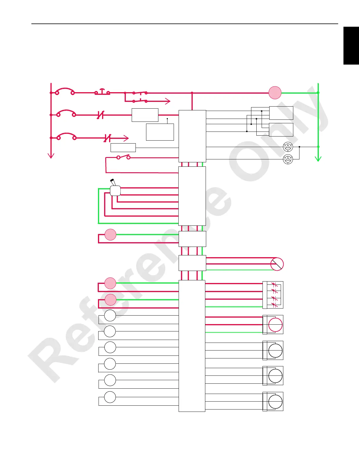
sends a 24 volt output to enable the selected jack cylinder
solenoid (HS-75 in this example) and shifts the valve to the
retract position.
The Node-3 controller also sends a variable 0 to 24 voltage
to enable the proportional relief solenoid HS-68 to provide
approximately 310 bar (4,496 psi) pressure to the jack
system.
76-a
76-E
76-S 24 Volts
AI
Gnd
76-b
AI
76-R
76-W
76-P
24 Volts
DI
Gnd
76-R
76-W
76-J
24 Volts
DI
Gnd
76-T
76-U
76-c
24 Volts
AI
Gnd
76-T
76-U
76-d
24 Volts
AI
Gnd
74-A
74-B
74-D
74-E
74-C
74-H
74-J
74-G
74-R
74-P
74-L
74-N
74-M
74-S
74-K
74-F
Gnd
Gnd
Gnd
Gnd
Gnd
Gnd
Gnd
Gnd
DO
DO
DO
DO
DO
DO
DO
DO
FIGURE 1-49
Left Front Jack
Cylinder
Sensor
MAX-ER Base Level
Sensor
+
–
PWR
CAB
System Fault Alarm
RCL Cab Fault Alarm
P11-07
P11-19
Display 1
Display 2
P11-01
P12-31
P12-32
P11-21
Start
WCP
CAN Power
Run 3
P12-24
Cab Power
Engine Stop
10 Amp
50 Amp
24 Volts
50 Amp
6C5A
6C5
CB7
6A
6C7
6C14
CB5
CB8
8C
8
NODE 0
NODE 1
(Master)
Hand-Held
Wireless
Remote
A
B
C
D
1
4
3
Mag
SW
Left Rear Jack
Cylinder
Sensor
1
4
3
Mag
SW
Right Front
Jack Cylinder
Sensor
1
4
3
Mag
SW
Right Rear
Jack Cylinder
Sensor
1
4
3
Mag
SW
HS
75
Left Front Jacking
Cylinder Extend
HS
74
HS
Left Front Jacking
Cylinder Retract
Left Rear Jacking
Cylinder Extend
Left Rear Jacking
Cylinder Retract
Right Front Jacking
Cylinder Extend
Right Front Jacking
Cylinder Retract
Right Rear Jacking
Cylinder Extend
Right Rear Jacking
Cylinder Retract
HS
76
HS
68
34-C
34-D
Accessory System
Proportional Valve
46-g
Accessory System
Pressure Sensor
46-j
46-h
Hyd
psi
24 Volts
AI
Gnd
2
3
1
NODE 3
HS
77
HS
79
HS
81
HS
80
HS
78
M16-03
NODE 7
Jacking Cylinders
Gnd
DO
NODE 4
Left Travel
Control Handle
DO P52-27
DI P51-17
DO P52-26
5 Volts P52-39
AI P51-13
Gnd P51-22
DI P12-26
D0 52-32
Seat Switch
NODE 2
P11-16
NODE 1
(Master)
CONFIRM