Manitowoc Published 05-03-17, Control # 228-03 1-67
16000 SERVICE/MAINTENANCE MANUAL INTRODUCTION
When the desired extension is reached, release the switch to
lock the cylinder in position. Hydraulic fluid at the piston end
of the cylinder counterbalance valve holds lift cylinder in the
selected position.
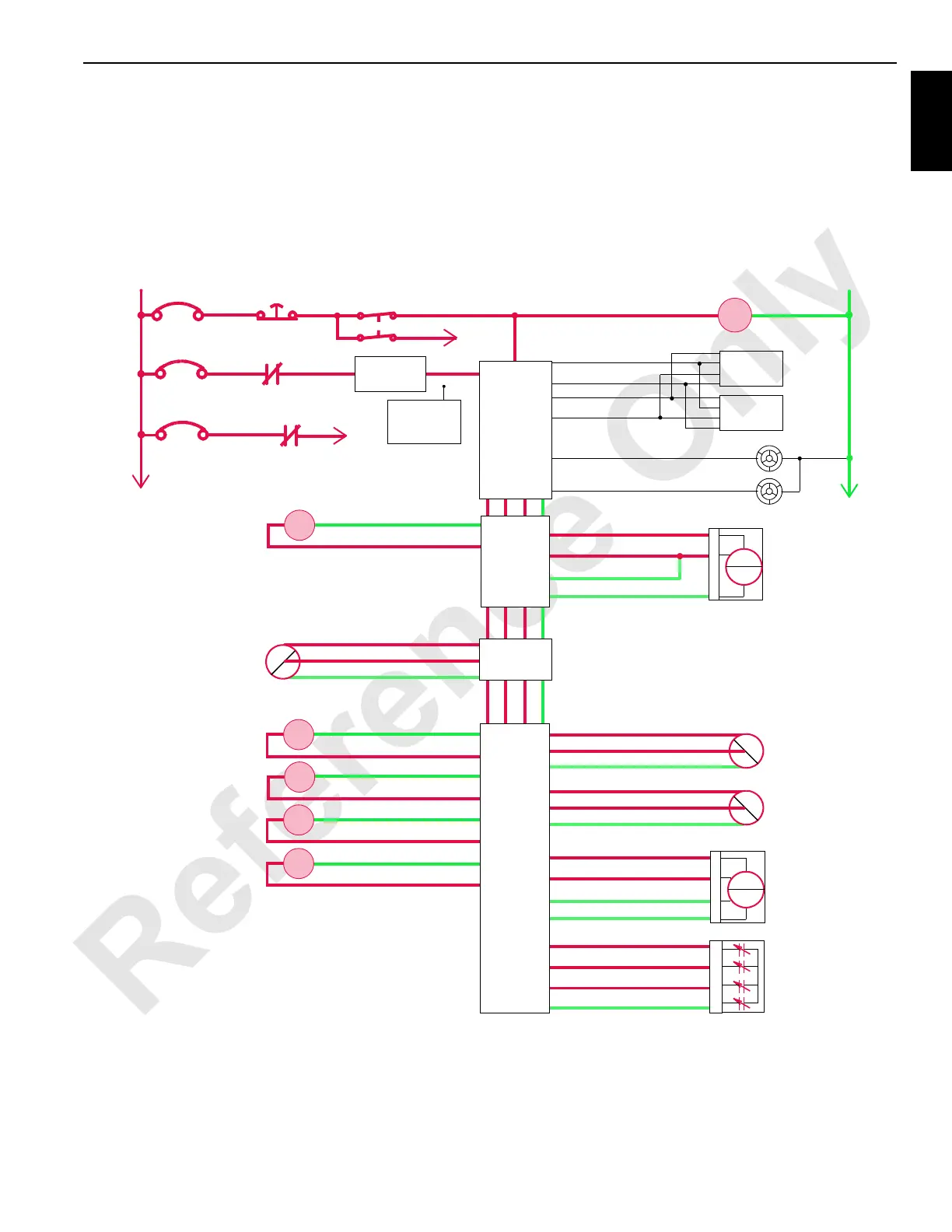
When the switch is released, an input signal is sent to the
Node-1 controller. The Node-7 controller sends a zero volt
output to the hydraulic solenoids HS-70 and 71 to the return
valve to the center position.
Node-3 sends a variable voltage output to the accessory
system proportional relief solenoid HS-68 to provide
approximately 207 bar (3,002 psi) system pressure.
RM-02
Counterweight Lift
Cylinder Extend
Pressure Sensor
MAX-ER Base Level
Sensor
+
–
PWR
CAB
System Fault Alarm
RCL Cab Fault Alarm
P11-07
P11-19
Display 1
Display 2
P11-01
P12-31
P12-32
P11-21
Start
WCP
CAN Power
Run 3
P12-24
Cab Power
Engine Stop
10 Amp
50 Amp
24 Volts
50 Amp
6C5A
6C5
CB7
6A
6C7
6C14
CB5
CB8
8C
8
NODE 0
NODE 1
(Master)
73-U
Counterweight Lift
Cylinder Retract
Pressure Sensor
73-E
73-a
Hyd
psi
73-V
73-A
73-c
Hyd
psi
24 Volts
AI
Gnd
24 Volts
AI
Gnd
76-a
76-E
76-S 24 Volts
AI
Gnd
76-b
AI
73-X
73-N
73-d
24 Volts
AI
Gnd
73-N
AI
Counterweight Lift
Cylinder Position
Sensor
Mag
LD
2
3
1
A
B
C
D
2
3
1
A
B
C
D
HS
72
HS
70
73-G
73-D
73-C
73-B
73-D
73-B
73-C
Counterweight Lift
Cylinder Extend
73-G
HS
73
HS
71
Counterweight Lift
Cylinder Extend
Counterweight Lift
Cylinder Retract
Counterweight Lift
Cylinder Retract
NODE 7
HS
68
Gnd 34-C
DO 34-D
Accessory System
Proportional Valve
46-g
Accessory System
Pressure Sensor
46-j
46-h
Hyd
psi
24 Volts
AI
Gnd
2
3
1
M16-12
36-m
36-J
36-k
24 Volts
AI
Gnd
36-Z
Gnd
Mast Strap
Load Pin
Load
Pin
A
B
D
NODE 3
Hand-Held
Wireless
Remote
Counterweight Lift Cylinder
DO
DO
DO
DO
Gnd
Gnd
Gnd
Gnd
NODE 4
FIGURE 1-53
 Loading...


