OPERATING CONTROLS AND PROCEDURES 2250 OPERATOR MANUAL
3-54
Published 06-24-16, Control # 241-01
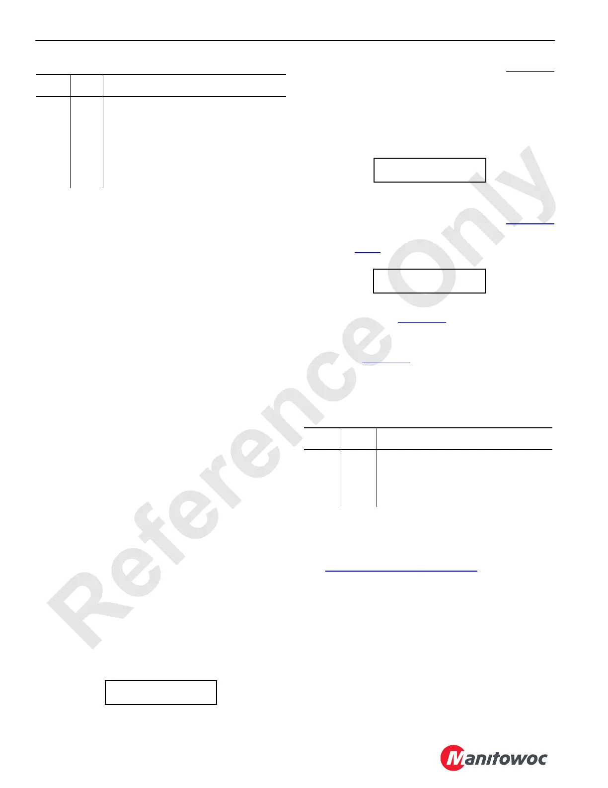
Table 3-3. Pressure Sender Binary Numbers
6. Before replacing a pressure sender, bleed the pressure
on the corresponding pump.
NOTE: The cause of a failed calibration or faulty display
pressure reading in the cab may not be the
pressure sender. The cause of the fault could be
trapped air or hydraulic pressure in the system.
a. Attach an accurate hydraulic pressure gauge to the
quick-coupler at the suspect pressure transducer
(see Section 2 of the Service Manual).
b. If pressure appears on the gauge, bleed the
corresponding system so the gauge reads zero
pressure.
c. Repeat the calibration steps and check the pressure
on the display in the cab with the engine running at
idle. The display reading and the gauge reading
should be the same.
d. Before replacing a pressure sender, check the
signal voltage at the sender. It should be 1.0 volt
against ground at 0 psi.
Controls Calibration
The controls must be calibrated at the following intervals:
• When a pump is replaced
• When a pump control (EDC or PCP) is replaced
• When a new programmable controller is installed
• When a new CPU board is installed
• When a new controller chip is installed
• When there is a noticeable increase in the time it takes a
crane function to engage when the handle is pulled back
from OFF
• Every six months
To calibrate the controls, proceed as follows:
1. Access the diagnostic screens by pressing the limit
bypass switch while scrolling up with the scroll switch.
2. Scroll until the Control Calibration screen in Figure 3-33
appears.
3. Increase engine speed to high idle and press the limit
bypass switch.
NOTE: It is normal for the yellow operating limits light to
come on during this procedure.
4. Calibration will not start if the engine is not at high idle.
Calibration will stop if engine speed is decreased during
calibration. In either case, the screen in Figure 3-34
appears.
5. Repeat step 3
.
6. When calibration starts, the Percentage of Completion
screen appears (Figure 3-35
). It takes approximately
two minutes to complete the process.
When calibration is complete, the Control Calibration
screen in Figure 3-33
reappears.
7. Check the data bank in the upper right corner of the
screen. If a control/pump fails the test, the binary
number(s) of the failed item(s) is displayed.
Table 3-4. Controls Binary Numbers
DIGITAL DISPLAY READINGS
General
See C4—Digital Display on page 3-18 for the following
information.
The digital display and selector allow the operator to monitor
the following three groups of crane information:
• Operating conditions
• Operating limits
• System faults
Press the top or bottom of the selector to scroll up and down
through the display readings. Release the selector when the
desired information is displayed.
Binary
No.
Pump
No.
Description
1 1 System Pressure (main hoist)
2 3 System Pressure (swing left)
4 3 System Pressure (swing right)
8 1 Charge Pressure (main hoist)
16 2 System Pressure (boom and luffing drums)
32 4 System Pressure (travel/drum 9 on MAX-ER)
64 5 System Pressure (left travel)
128 0 System Pressure (independent luffing)
FIGURE 3-33
CONTROL CALIBRATION
BYPASS TO BEGIN
Binary
No.
Pump
No.
Description
1 1 Main Hoist
2 2 Boom and Luffing Drums
4 3 Swing Right
8 3 Swing Left
16 4 Drum 9 on MAX-ER
FIGURE 3-34
CONTROL CALIBRATION
HIGH IDLE REQUIRED
FIGURE 3-35
CONTROL CALIBRATION 6
___% COMPLETE