SETUP AND INSTALLATION 2250 OPERATOR MANUAL
4-82
Published 06-24-16, Control # 241-01
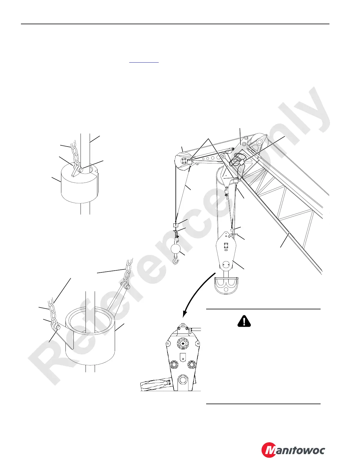
Install Block-Up Limit Control and Connect
Electric Wiring
Install the block-up limit components (see Figure 4-46 and
Block-Up Limit Control Assembly drawing).
1. Connect the electrical cable from the cable reel in the
boom butt to the junction box in the boom top.
2. Connect the electrical cable from the front of the crane to
the cable reel.
3. Connect the electrical cables from the limit switches to
the junction box in the boom top.
4. Adjust the block-up limit switches according to the
instruction in Section 5 of the Crane Service Manual.
5. Connect the electrical cables from the rated capacity
limiter (RCL) load-sensing sheaves to the junction box in
the boom top. See the Indicator Assembly drawing.
6. Check the RCL operation and calibration as instructed in
the RCL Operation Guide.
A1050
Limit Switch
Assembly
Weight
Lift Block
Weight Ball
Load Block
Chain
Weight
Lift
Plates
Upper Boom
Point
Lower Boom
Point
#44 Boom
#44 Boom with Jib Similar
Chain
Junction Box
Electrical Cord
to Reel on
Boom Butt
A1050
Chain
Shackle
Weight
Connecting
Pin
Dead-End Load Line
or Slowest Live Line
Chain
Shackle
Weight
Connecting
Pin
Two Chains Prevent
Weight from Turning
Lower Boom Point (multiple part),
#132 or #140 Fixed Jib (4 part),
Extended Upper Boom Point (4 part), or
Lower Luffing Jib Point (multiple part)
#132 Fixed Jib (1-3 part),
Standard or Extended Upper Boom Point
(1-3 part), Upper Luffing Jib Point (1 part)
WARNING
Tipping Hazard!
Prevent the possibility of being crushed or
seriously injured. Exercise care when the
load block is standing in the vertical
position, since the potential for tipping
exists.
Potential causes of tipping are unstable
work area, boom movement, and the
reeving process. If work area is unstable,
lay the block flat on the side plate.
FIGURE 4-46