Manitowoc Published 06-24-16, Control # 241-01 4-45
2250 OPERATOR MANUAL SETUP AND INSTALLATION
Make Cab-to-Machine Connections
See Figure 4-24 for the following procedure.
The cab tower is shipped with piping and wiring installed in
the vertical wiring trough. Connections to the cab can be
made from the service deck. Connections to the machine are
made in the horizontal wiring trough at the base of the tower.
1. If necessary, remove the cover from the horizontal wiring
trough.
2. Make the air piping connections. All air hoses have quick
disconnects.
a. At the service deck, connect hoses TA1, TA2, and
TA3 from the wiring trough to the connectors CA1,
CA2, and CA3, respectively, on the air manifold (see
View B).
b. At the horizontal wiring trough, connect the hoses
TA1, TA2, and TA3 to connectors MA1, MA2, and
MA 3, respectively, on the machine (see View C).
3. Make the electrical connections.
a. At the service deck, connect the electrical cables
from the wiring trough to the terminals at the cable
bulkhead (see View D). Cable numbers will match
the terminal numbers.
b. At the horizontal wiring trough, connect the
electrical cables from the wiring trough to the cables
from the machine. The cables have matching
numbers.
4. Connect the cab exterior lighting to the junction boxes
(Figure 4-25
).
a. Connect the cable from the wiring trough to junction
box A on the back of the cab (see View B).
b. If necessary, plug the front floodlights and ladder
floodlight into junction box A (see View B).
c. Connect the cable from the wiring trough to junction
box B under the catwalk (see View A).
d. Plug the receptacle and cold-weather package
(if provided) into junction box B (see View A).
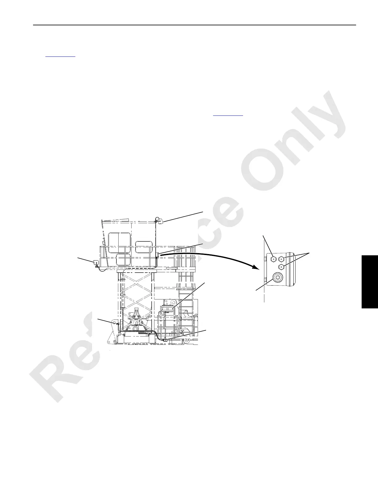
FIGURE 4-25
A1222
View A
Junction
Box A
Ladder
Floodlight
Front
Floodlights
(two places)
Receptacle
Junction
Box B
View B
(bottom view)
To Ladder
Floodlight
To Junction
Box B
To F r ont
Floodlights
Cold-Weather
Package
(optional)