OPERATING CONTROLS AND PROCEDURES 2250 OPERATOR MANUAL
3-72
Published 06-24-16, Control # 241-01
• Use the left pedal (right rear drum) to apply the drum
working brakes.
• Use the control handle corresponding to the drum that
has the load line installed on it. This will reduce torque
on the drive lug.
Full Power Mode
Use the drum interlock in the Full Power mode when the
added security of a dual park brake and clutch application is
desired during critical lifts.
Drum interlock in the Full Power mode only requires
installing a drive lug between the drums. It is not necessary
to modify or reroute the drum working brake air lines,
because in the Full Power mode, the drum park brake stops
the drum. The drum working brake is used only when
necessary to stop the drum. One working brake has
sufficient torque to perform this function.
Drum interlock in the Full Power mode requires the drums to
be operated in the tandem drum mode. In Tandem mode, the
crane’s programmable control automatically selects the left
side control handle (right drum) as the active handle. The
other handle is inoperable.
Installing Drum Interlock
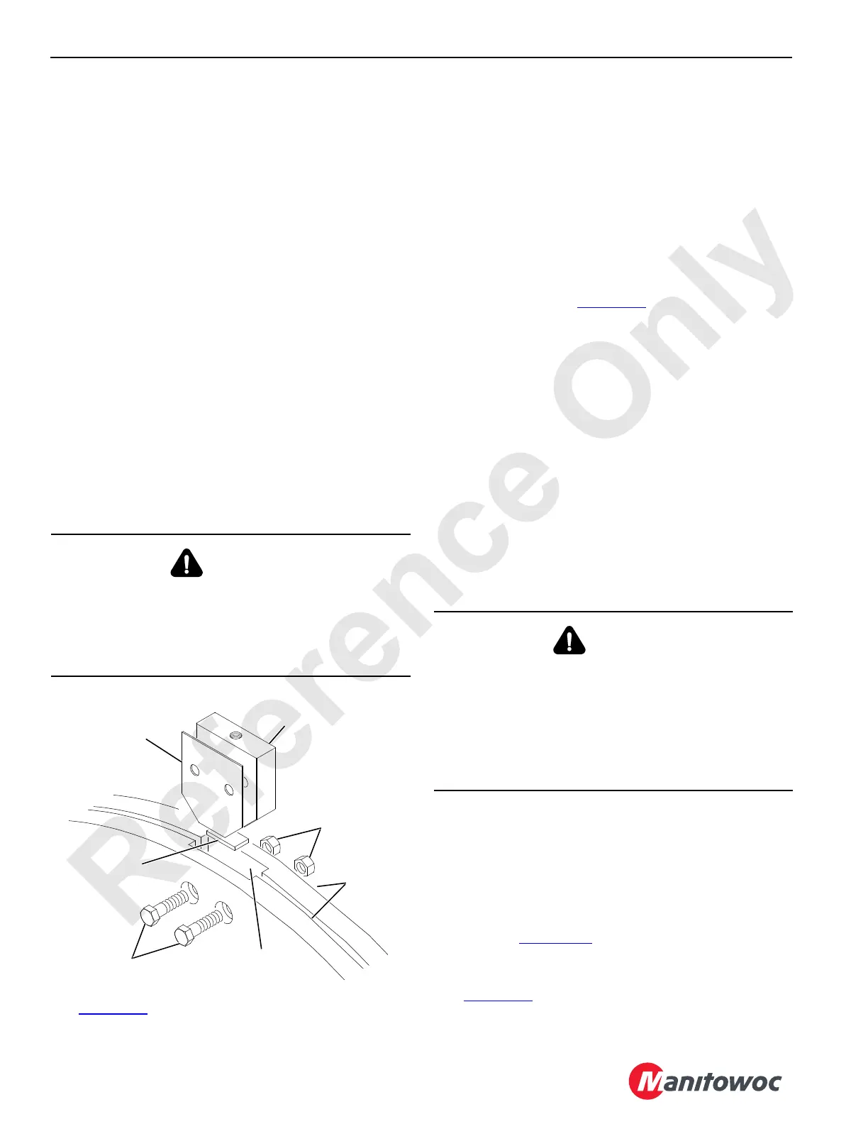
See Figure 3-56 for the following procedure.
1. Land the load on both drums so the wire rope is slack.
2. Remove the load line from the drum not to be used.
3. Operate the drums to align the keyways in the drum
flanges as shown.
4. Install the flat bar and drive lug in the keyways as shown.
Use shims so the drive lug is snug in the keyways.
5. Apply thread-locking compound to the screw threads,
fasten the nuts to the screws, and securely tighten the
nuts so they cannot loosen.
6. Modify the drum working brake air lines to allow drum
interlock operation (Figure 3-58
, View B).
This modification is not required for operation in the Full
Power mode, but it can be made if dual working brake
operation is desired.
a. Fully release both drum working brake pedals to
exhaust air from the air lines between the brake
chambers and the treadle valves.
b. Install a tee (1) in air line B with nuts (3) and ferrules
(2).
c. Connect jumper air line C to the tee (1) with a nut (3)
and ferrule (2).
d. Securely fasten the female connector (4) and plug
(5) to the free end of air line A with a nut (3) and
ferrule (2).
e. Make sure all fittings are tight to prevent air leaks.
Removing Drum Interlock
1. Land the load on both drums so the wire rope is slack.
2. Fully release both drum working brake pedals to exhaust
the air from the air lines between the brake chambers
and treadle valves.
3. Remove the drive lug, shims, and flat bar from the
keyways (Figure 3-56
). Store all parts.
4. If the drive lug is seized to the keyways, use a bar and
bolt to jack the drive lug out of the keyways
(Figure 3-57
).
WARNING
Falling Load Hazard!
Avoid the possibility of death or serious injury. The load
will fall if the load lines are not slack. Land all loads so the
load lines are slack before installing the drive lug or
disconnecting the air lines.
FIGURE 3-56
A583
Shims
Drive Lug
Nuts
Flat Bar
Capscrews
Keyways
Drum
Flanges
WARNING
Falling Load Hazard!
Death or serious injury to personnel can result. The
working brake must be applied to stop the load when the
drum control handle is released to OFF. Otherwise, the
load will lower uncontrolled.
Be aware of which working brake pedal is active when
operating with drum interlock in Free Fall mode.