OPERATING CONTROLS AND PROCEDURES 2250 OPERATOR MANUAL
3-14
Published 06-24-16, Control # 241-01
A—Engine Controls
See Figure 3-4 for the following components.
NOTE: Engine start and speed controls are mounted
remotely on a junction box on the right side of the
rotating bed. See Remote Controls on page 3-51
for operation of the remote controls.
A1—Engine Run/Stop/Run Key Switch
Insert the key and turn it to either RUN position to turn on the
crane’s electrical system.
Turn the key to the STOP position to stop the engine and turn
off the crane’s electrical system.
NOTE: Stopping the engine in an emergency will cause all
brakes to apply and any operating functions to
stop. Be aware that functions will stop abruptly.
A2—Engine Start Switch
Turn the knob clockwise and hold it to start the engine.
Release the knob as soon as the engine starts.
NOTE: The Engine Run/Stop/Run key switch must be in
the proper RUN position before the engine can be
started. If the engine does not crank, turn the
Engine Run/Stop/Run key switch to the other RUN
position.
The digital display will come on when the Engine
Run/Stop/Run key switch is in the proper position.
The digital display will go off while the engine is
starting.
A3—Engine Lights
Two engine lights are provided, as follows:
Engine Stop Light (red)
If this light comes on, stop the engine as soon as
safely possible.
Engine Warning Light (amber)
If this light comes on, repair the engine fault at the
first available opportunity.
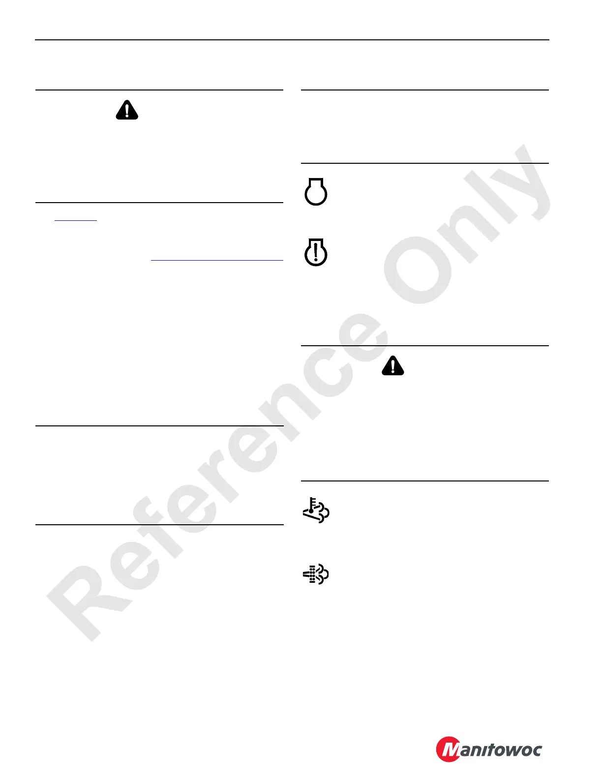
A4—Exhaust System Lights
Three amber lights are provided, as follows:
High Exhaust System Temperature
When on, this light indicates that higher than normal
exhaust temperatures exist, normally due to diesel
particulate filter (DPF) regeneration. It is normal for
this light to come on during normal operation.
Diesel Particulate Filter (DPF) Regeneration
This light displays one of the three following
conditions:
• When on, this indicates that the exhaust after-treatment
system requires regeneration within the next few hours.
Use the diesel particulate filter (DPF) switch to start a
manual regeneration cycle.
• If flashing, the DPF is in regeneration mode. The
operator may sense a reduction in power. No immediate
action is required.
• If flashing and the red engine stop light is on,
regeneration is required but is inhibited. The operator
WARNING
Startup Hazard!
Avoid the possibility of death or serious injury. Avoid
unauthorized startups.
Always remove the key before leaving the crane
unattended. This practice will prevent unauthorized
personnel from starting the engine.
CAUTION
Avoid Engine Damage!
Use of any starting aids can result in an explosion and
personal injury. Do not use aerosol starting aids such as
ether.
See the Engine Manual for cold weather starting
instructions and precautions.
CAUTION
Engine Damage!
Avoid engine damage. If this red light comes on, lower all
loads and then stop the engine as soon as possible. Do
not run the engine until the fault is corrected.
WARNING
Burn Hazard!
Avoid high exhaust temperature and the possibility of a
serious burn. Active diesel particulate filter (DPF)
regeneration can occur at low engine idle as well as
during crane operation. This may result in high exhaust
temperature.
Always keep personnel well away from the exhaust to
prevent injury.