Manitowoc Published 06-24-16, Control # 241-01 3-13
2250 OPERATOR MANUAL OPERATING CONTROLS AND PROCEDURES
A—Engine Controls C2 Load Indicator Console E12 Dome Light Dimmer Control (optional)
A1 Engine Run/Stop/Run Key Switch C3 Crane Level Display E13 Clam Closing Control and Air Pressure
Gauge
A2 Engine Start Switch C4 Digital Display
A3 Engine Lights C5 Digital Display Selector Switch E14 APU Cab Key Switch (optional)
A4 Exhaust System Lights C6 Operating Limit Alert F—Boom/Luffing Hoist Controls
A5
Diesel Particulate Filter (DPF)
C7 System Fault Alert F1 Boom Hoist Handle
Switch C8 Rotation Indicators F2 Drum 4 Park Switch
A6 Diesel Exhaust Fluid (DEF) Gauge C9 Wind Speed Indicator F3 Drum 5 Park Switch
and Light C10 Engine Hour Meter G—Load Drum Controls
A7 Emergency Stop Switch C11 Boom Angle Indicator G1 Left Handle
A8 Engine Foot Throttle C12 Drum Direction Indicator G2 Right Handle
A9 Engine Hand Throttle D—Gauges G3 Drum 1 Park Switch
A10 Pump Drive Disconnect Handle D1 Hydraulic Tank Temperature Display G4 Drum 2 Park Switch
A11 Battery Disconnect Switch D2 Fuel Level Gauge G5 Drum 3 Park Switch
B—Accessory Controls D3 Engine Water Temperature Gauge G6 Left Working Brake Pedal
B1 Tinted Visor D4 Engine Oil Pressure Gauge G7 Right Working Brake Pedal
B2 Defroster Fan D5 Battery Voltage Gauge G8 Drum 9 Park Switch
B3 Horn Switch D6 Air Pressure Gauge G9 Auxiliary Drum 5 Handle (optional)
B4 Dome Light Switch E—Special Controls and Indicators H—Swing Controls
B5 Air Conditioner Temperature Selector E1 Drum 1 Free Fall Light H1 Swing Handle
B6 Air Conditioner/Heater Switch E2 Drum 2 Free Fall Light H2 Swing Holding Brake Switch
B7 Air Conditioner/Heater Fan Switch E3 Drum 3 Free Fall Light H3 Swing Brake Switch
B8 Panel Lights Switch E4 Crane Mode Selector J—Travel Controls
B9 Windshield Washer Switch E5 Limit Bypass Switch J1 Left Crawler Handle
B10 Front Windshield Wiper Switch E6 Drum Selector J2 Right Crawler Handle
B11 Overhead Windshield Wiper Switch E7 Load Drum Indicator Lights J3 Travel Detent Selector
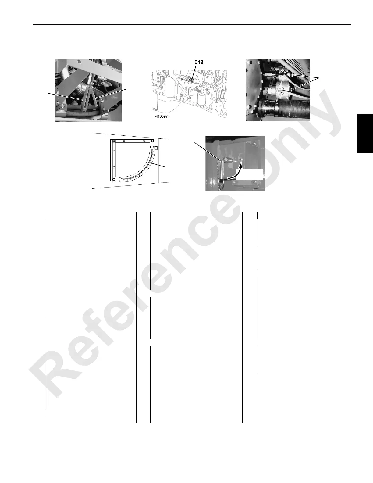
B12 Engine Block Heater E8 Seat Switch J4 Travel Park Switch
B13 Hydraulic Oil Heaters E9 MAX-ER Controls J5 Travel Speed Selector
C—Indicators E10 Aircraft Warning Beacon (optional)
C1 Mirrors E11 Dome Light (optional)
C11
P589
View at Pumps
Inboard Side of
A10
Right Side of Engine
Hydraulic Tank
View at Boom Butt
(right leg)
A486
(left side of upper)
Trigger
B13
Thermostat
(under cover)
P693
FIGURE 3-4 continued
A11
P6734M
Shown in Connected (closed) Position
Right Side Enclosure
(near batteries)