SETUP AND INSTALLATION 2250 OPERATOR MANUAL
4-38
Published 06-24-16, Control # 241-01
3. Rotate the front jacks to the horizontal “wing” position
(Figure 4-12
, View D). Pin the struts to the jacks
(Figure 4-8
, View A).
4. Swing the operator’s cab to the intermediate position
and pin in place (Figure 4-10
).
5. Rotate the rear jacks to the operating position
(Figure 4-8
). Pin the struts to jacks.
6. Install the jack pads (Figure 4-7
, View E).
7. Extend the rear jacks until the carbody pedestals can be
installed.
Remove two pedestals from storage (Figure 4-7
,
View B) and install them under the carbody (Figure 4-12
,
View A).
NOTE: Make sure the pedestals engage the support pads.
8. Retract the rear jacks and rotate to the horizontal “wing”
position (Figure 4-19
, View C).
9. Swing the rotating bed over the other crawler.
10. Repeat step 5
, through step 7 for the remaining two
carbody pedestals.
11. Ensure the carbody is level. Adjust the jack screws to
the level assembly (Figure 4-12
, View A).
Remove Crawlers
1. Position an empty trailer along the desired side of the
carbody (Figure 4-17
).
2. Start the engine. Swing the rotating bed and boom up so
that the assembly block is centered over the crawler.
3. Connect the crawler handling chain assembly to the
hook of the assembly block.
4. Unpin the drive shaft guard (Figure 4-18
, View D) and
slide the guard back.
5. Remove the flange screws from the drive shaft flange
(Figure 4-18
, View C). Store the screws in the flange.
6. Retract the crawler drive shaft and place the drive shaft
on the supporting bracket (Figure 4-18
, View B).
7. Connect three legs of the chain assembly to the lugs on
the crawler frame (Figure 4-17
, View A).
8. Remove and store the retaining pins (Figure 4-18
,
View A) and disengage the crawler frame pins with the
control on the setup remote control. Pins should be fully
disengaged within 10 seconds.
9. Visually check that both crawler frame pins are fully
disengaged. If either pin fails to disengage, proceed as
follows:
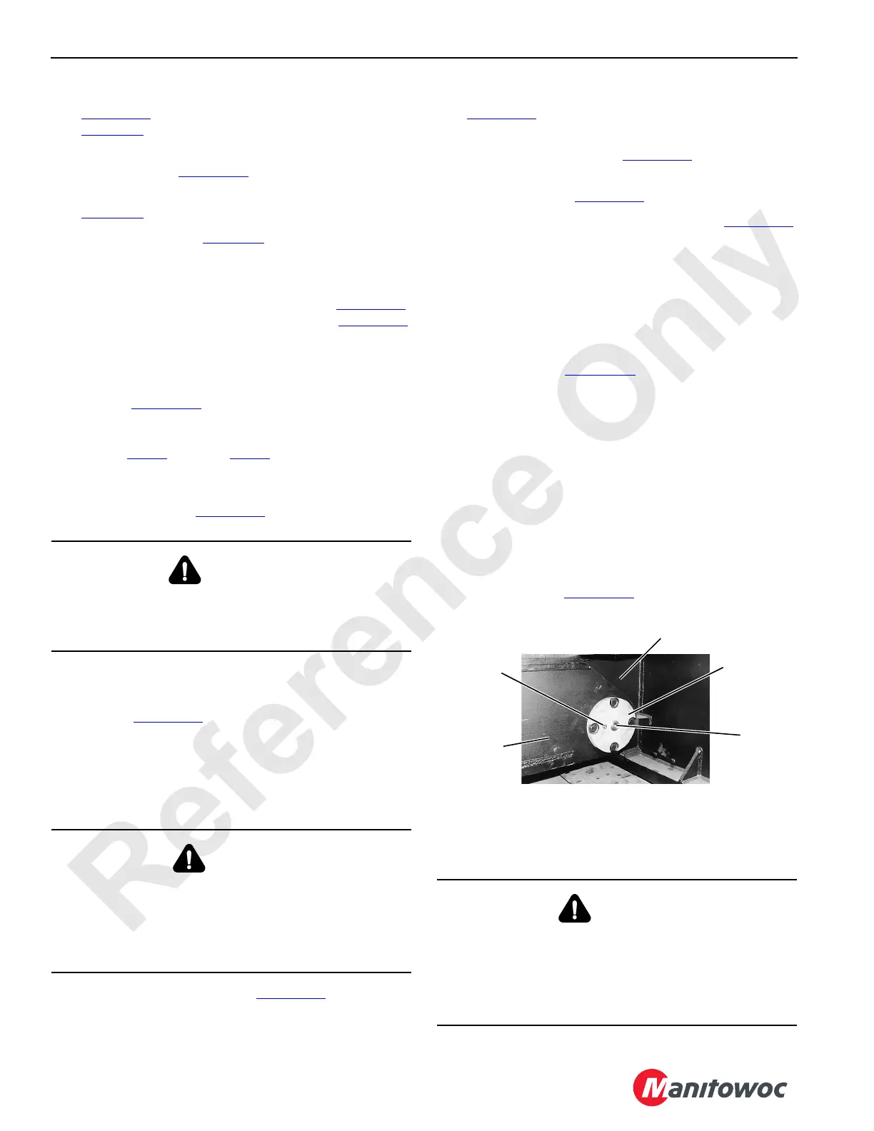
a. Pump grease into the grease fitting on the piston
cover plate (Figure 4-22
) while holding the crawler
frame pin switch at the disengage position for 10
seconds.
b. If the pin does not disengage, remove the plug from
the piston cover plate and measure the position of
the piston. When fully retracted, the piston is 25,7
cm (10-1/8 in) from the outside of the cover.
c. If the dimension is less than 25,7 cm (10-1/8 in)
remove the cover plate and, using a bar and
hammer, tap the piston until it is fully retracted
(check dimension). Replace the piston cover plate.
10. Lift the crawler. The crawler will tilt as it is lifted off the top
connecting pins (Figure 4-18
, View A).
11. Continue lifting the crawler. Stop before hitting the cab
support.
WARNING
Tipping Hazard!
Avoid possible injury. Level the assembly using a
carpenter’s level to avoid potential tipping.
DANGER
Rotating Drive Shaft Hazard!
The crawler drive shaft rotates at high speeds. To prevent
death or serious injury, do not attempt to disconnect the
drive shaft until the crane has been parked and the engine
has stopped.
DANGER
Falling Boom Hazard!
Avoid serious injury. The crane boom can collapse if not
properly lowered.
Carefully perform the following steps to properly lower the
boom and prevent it from falling suddenly.
FIGURE 4-22
Grease
Fitting
Carbody
Crawler Frame
Piston
Cover Plate
Plug
P619