Manitowoc Published 06-24-16, Control # 241-01 4-117
2250 OPERATOR MANUAL SETUP AND INSTALLATION
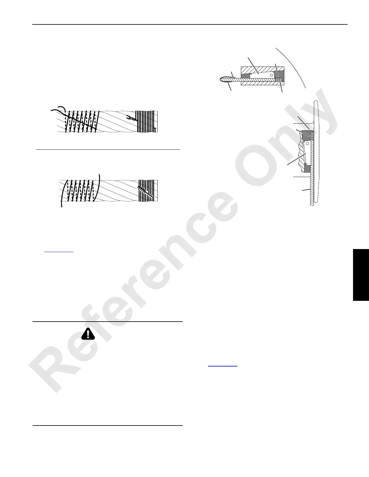
Anchoring Wire Rope to Drum
See Figure 4-63 for the following procedure.
Use the correct wedge part number for the size of wire rope
being used. See the parts drawing to obtain the correct part
number for the boom hoist drums or for the load drum shaft.
1. Assemble the wire rope and the wedge to the drum
socket.
2. Tighten the wedge, rapping the back of the wedge with a
brass drift pin and hammer.
Winding Wire Rope onto Drum
See the Drum and Lagging Chart in the Capacity Chart
Manual for the correct size of drum laggings, if used.
See the Wire Rope Specifications Chart in the Capacity
Chart Manual for the correct type, size, and amount of wire
rope to be installed on the load drums.
See the Boom Rigging drawing for the correct type, size, and
amount of wire rope to be installed on the boom hoist drums.
1. Carefully inspect the drums and all the rope guides,
rollers, and sheaves for defects that can cause the wire
rope to wear or be cut. If the defects cannot be fixed,
replace the faulty parts.
2. Apply tension to the wire rope as it is being wound slowly
onto the drum.
The first wrap must be tight against the drum flange for
approximately three-fourths of the drum diameter
(Figure 4-64
).
3. Tap the adjacent wraps against each other with a soft
metal or wooden mallet.
Use extreme care not to put twists or turns in the wire
rope. Allow the rope to assume its natural lay.
WARNING
Falling Load Hazard!
Prevent possible injury. Wire rope can be pulled out of the
drum if the following steps are not taken:
• Install a straight wedge so the corrugated side is
against the wire rope.
• Install the wedge so the end of the wire rope extends
past the end of the wedge, but not out of the drum
socket.
• Make sure seizing is not under the wedge. Remove
the seizing if it interferes with the assembly.
FIGURE 4-62
Place the free end of the seizing wire in the valley between the
two stands. Then wind the seizing wire over the free end as
shown. Finally, twist and pull the two ends of the seizing wire
together until the seizing is tight.
View A
A925
Rope Diameter 26 mm (1 in) and Larger
View B Rope Diameter Smaller than 26 mm (1 in)
Wind the seizing wire around the wire rope as shown. Then twist
the two ends of the seizing wire together at the center of the
seizing. Alternately twist and pull the ends until the seizing is
tight
.
Wire Rope Type
Seizings
Required
Preformed
1
Non-preformed
3
FIGURE 4-63
Hole in
Drum Flange
Straight Wedge
Inside Drum
Straight Wedge
Outside Drum
Do not allow the end of
the wire rope to extend
out of the socket
opening
Seizing
Seizing
Wire
Rope
Wire
Rope