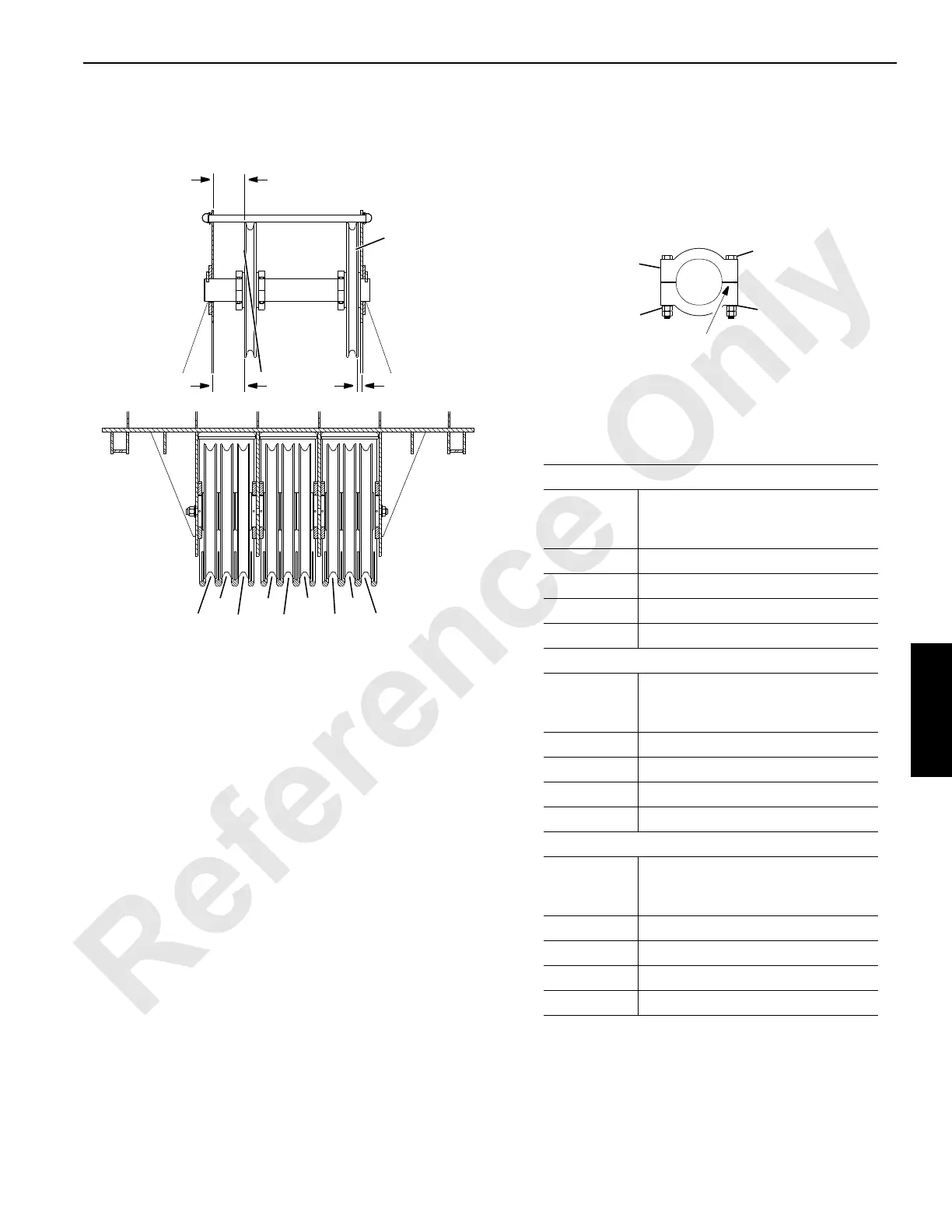
FIGURE 4-70
NOTE 1: Hand position the clamps tight against the bearing.
Before tightening the bolts, make sure that the sheave
turns freely. Tighten the bolts lubricated with SAE 20 oil
to 163 Nm (120 ft-lb).
NOTE 2: This location requires the sheave bearing to bear up
against the boom top plate as shown at Dimension B.
NOTE 3: This location requires four clamps as shown at
Dimension A.
Location of Guide Sheaves with Load Line
Going to Lower Boom Point Sheave Indicated
Right Rear Drum Sheave
Load Line
Reeving to
Sheave
Dimension B
S9 16 mm (0.62 in) NOTE 2
S8 52 mm (2.06 in) NOTE 3
S7 121 mm (4.75 in) NOTE 3
S6 265 mm (10.44 in) NOTE 3
Left Rear Drum Sheave
Load Line
Reeving to
Sheave
Dimension A
S4 240 mm (9.44 in) NOTE 3
S3 95 mm (3.75 in) NOTE 3
S2 16 mm (0.62 in) NOTE 2
S1 16 mm (0.62 in) NOTE 2
Front Drum Sheave
Load Line
Reeving to
Sheave
Dimension A
S4 271 mm (10.69 in) NOTE 3
S3 125 mm (4.92 in) NOTE 3
S2 52 mm (2.06 in) NOTE 3
S1 16 mm (0.62 in) NOTE 2
S1
AB
S3 S5 S7 S9
S2
S4 S6 S8
Tighten each side equally to provide an
equal gap. See NOTE 1 for torque value.
Clamp
Bolt
Nuts
Lock Washer
Left Rear
or
Front Drum
Right Rear Drum
A616
Lower Boom
Point Sheaves
Boom Top
Guide Sheaves
240 mm (9.44 in) for Left Rear Drum to Upper Boom Point, or
271 mm (10.69 in) for Front Drum to Upper Boom Point