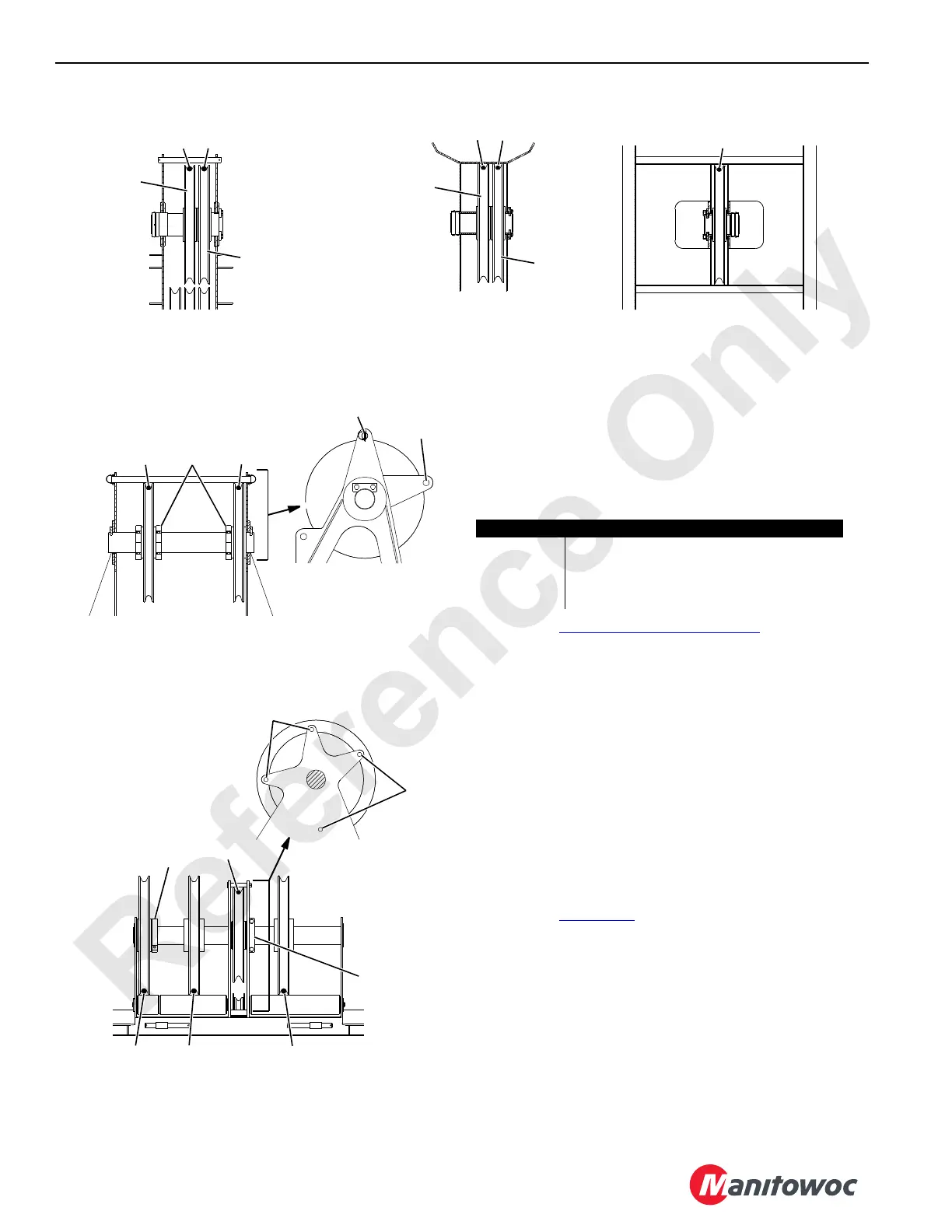
FIGURE 4-69
STANDARD LIFTCRANE
#44 or #44A Boom
NOTE 1: See Guide Sheaves on page 4-123 for the
identification of the 2250 with #44 or #44A Heavy Lift or
the Long Reach Boom.
Guide sheave identification for other attachments is
located in Operator Manual for the specific attachment.
Bold dots ( • ) indicate load line engagement with
sheaves when viewed from boom butt.
NOTE 2: Install the rope retaining pins in these holes for the
luffing hoist operation.
NOTE 3: Install the rope retaining pins in these holes for the
equalizer handling.
NOTE 4: For #132 jib operation, do not route the load line
through the guide sheave on the transition insert or on
the boom top. Route the desired load line through the
proper guide sheave on the boom butt and then directly
to the guide sheave on the jib strut.
NOTE 5: See
Figure 4-70 for guide sheave positioning.
NOTE 6: Install
the rope retaining pin in this hole for #44, #44A,
or #49A-#44 boom.
NOTE 7: Install the rope retaining pin in this hole for #49A-#44
boom with 133A luffing jib.
NOTE 8: Clamp must be installed when equipped with the equal
width split rear drums.
Sheave Load Line
1 Left Rear Drum
2 Right Rear or Rear Drum
3 Front Drum
4 Luffing Hoist
32
2
4
1
Boom Top
HEAVY LIFT BOOM
See
NOTE 6
See
NOTE 7
See
NOTE 3
See
NOTE 2
See
NOTE 5
Boom
Butt
1 or 3
Transition Insert
LONG REACH BOOM
#132 Jib Strut
See NOTE 4
Boom Top
LONG REACH BOOM
See
NOTE 8
2
1
or
3
Clamp
1 or 32
1 or 3
A791
To L ow e r
Boom Point
To Upper
Boom Point
To Lower
Boom Point
To U pper
Boom Point