Manitowoc Published 06-24-16, Control # 241-01 4-101
2250 OPERATOR MANUAL SETUP AND INSTALLATION
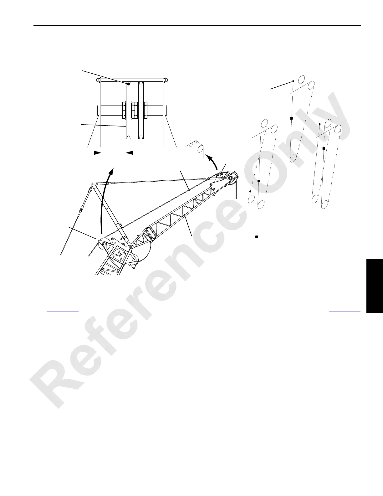
Install Load Line
See Figure 4-54 for the proper routing and reeving of the
load line to the extended upper boom point. The left guide
sheave in the boom top is used for routing the load line to the
extended upper point.
NOTE: The sheave must be positioned as shown in
View B.
Load lines must be properly routed through the
RCL load-sensing sheaves as shown in the reeving
diagrams.
Install Block-Up Limit Control and Connect Wiring
Install block-up limit components as shown in Figure 4-46
and in Block-up Limit Control Assembly drawing.
1. Connect the electrical cable from the jib to the junction
box in the boom top.
2. Connect the electrical cable from the limit switch to the
junction box in the upper boom point.
3. Adjust the block-up limit switch according to the
instructions in Section 5 of the Crane Service Manual.
4. Connect electrical cables from the rated capacity limiter
(RCL) load-sensing sheaves to the junction box in the
boom top. See the Indicator Assembly drawing.
5. Check the RCL operation and calibration as instructed in
the RCL Operation Guide.
Extended Upper
Boom Point
Load Block
A483
View B
4 PART3 PART
2 PART
Wire
Rope
338 mm
(13-5/16 in)
(viewed from cab)
Left
Sheave
FIGURE 4-54
Suggested Location of Weight
for Block-Up Limit Control
=
Dead-End
Wedge Socket
View C
Reeving
A1143
View A
Wire
Rope
Extended Upper
Boom Point
Boom Top
Wire Rope
Guide
Load
Sensing
Sheaves