SETUP AND INSTALLATION 2250 OPERATOR MANUAL
4-72
Published 06-24-16, Control # 241-01
BOOM RIGGING GUIDE (#44 HL AND LR)
General
This topic contains installation and removal instructions for
#44 and #44A Heavy Lift and #44 Long Reach booms
equipped with straps.
Assist Crane Requirements
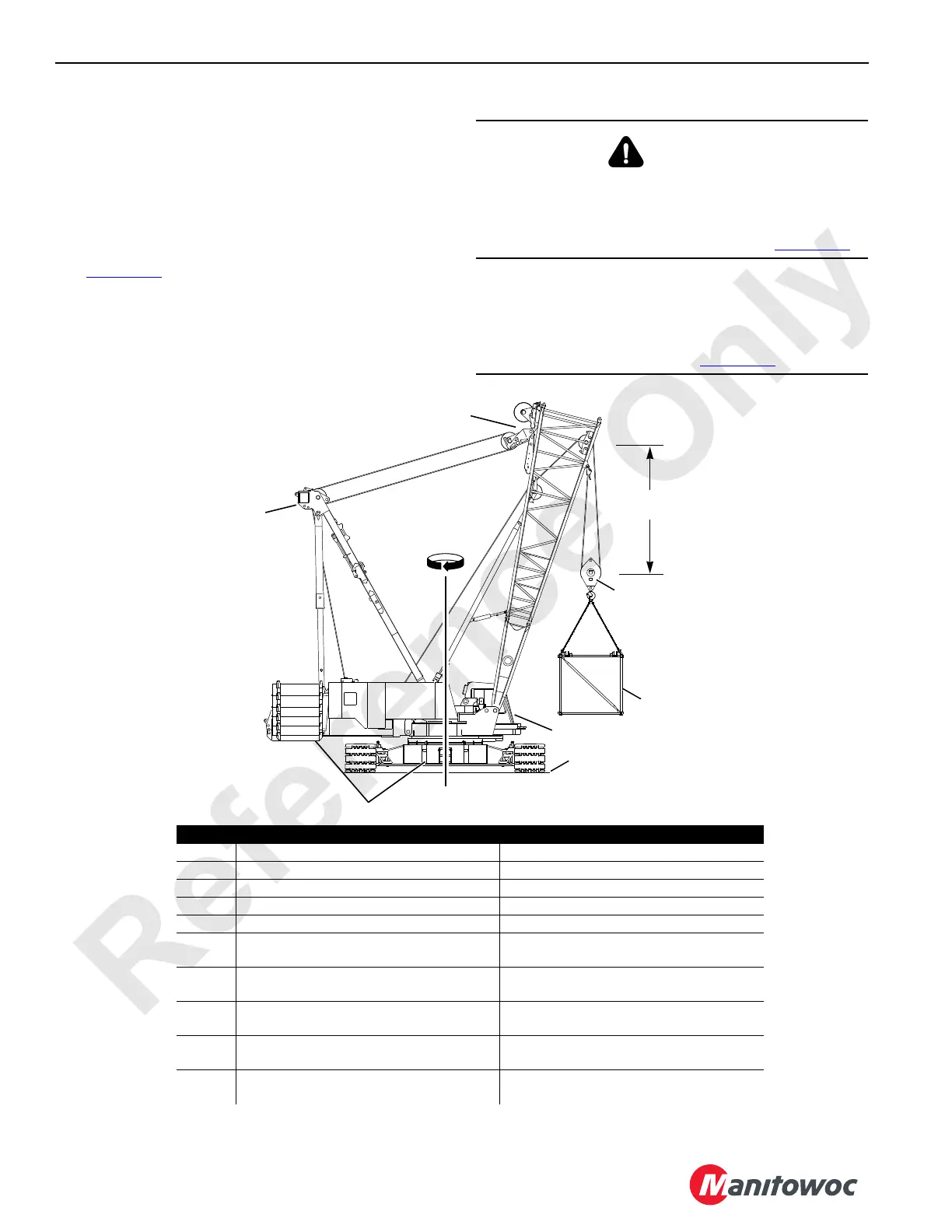
See Figure 4-39 for the following information.
An assist crane is not required to assemble and disassemble
the boom sections. The 2250 crawler or truck crane can be
used to assemble and disassemble its own boom sections
when the crane is equipped with self-erect guide sheaves in
the boom butt and is configured as shown.
DANGER
Tipping Hazard!
Avoid serious injury. To prevent the crane from tipping or
the boom butt from collapsing, do not exceed the
maximum lifting capacity and radius given in Figure 4-39
.
CAUTION
Avoid Damage to Boom Rigging!
Hoisting the block higher than specified can result in
damage to the wire rope and sheaves. Do not exceed the
minimum block distance given in Figure 4-39
.
FIGURE 4-39
A1048
Item Configuration
DescriptionCrawler Crane DescriptionTruck Crane
A Gantry Fully Raised Gantry Fully Raised
B Counterweight Installed or Removed Counterweight Removed
C 360° Swing and Travel Permitted 360° Swing and Travel Permitted
D 5,2 m (17 ft) Minimum Block Clearance 5,2 m (17 ft) Minimum Block Clearance
E 27,2 t (30 USt) Rigging Block
with 2-Part Hoist Line
27,2 t (30 USt) Rigging Block
with 2-Part Hoist Line
F Capacity Limited to 27 216 kg (60,000 lb) at
6,1 m (20 ft) Radius
Capacity Limited to 22 226 kg (49,000 lb) at
6,7 m (22 ft) Radius
G Crane Operated on a Firm, Level, Uniformly
Supporting Surface
Crane Operated on a Firm, Level, Uniformly
Supporting Surface
H Standard Mode Selected and Confirmed (in
crane cab)
Standard Mode Selected and Confirmed (in
crane cab)
Not
Shown
Not Applicable Outriggers Installed (retracted)
Crane Operated on Rubber
B
Crawler Crane Shown
Truck Crane Similar
Equalizer Pinned
to Boom Butt Rails
D
E
F
G
H
C
A
B