OPERATING CONTROLS AND PROCEDURES 2250 OPERATOR MANUAL
3-88
Published 06-24-16, Control # 241-01
Control Panel
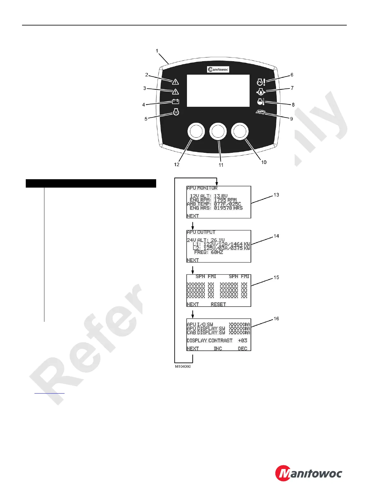
See Figure 3-68 for the following information.
The control panel (1) can be used to display the status and
diagnostic information of the APU to the user. On each side
of the display there are four back-lit symbols—all eight are
illuminated for one second at startup.
• Warning Symbol (red) (2)—This warning symbol is
illuminated when faults are present that prevent the APU
from starting.
• Warning Symbol (amber) (3)—This warning symbol is
illuminated when faults are present that prevent the APU
from being fully functional.
• Battery Symbol (red) (4)—The battery symbol is
illuminated when the charging system is not operational.
FIGURE 3-68
Item Description
1 Control Panel
2 Warning Symbol (Red)
3 Warning Symbol (Amber)
4 Battery Symbol (Red)
5 Glow Plug Symbol (Amber)
6 Engine Failure Symbol (Red)
7 Engine Oil Pressure Symbol (Red)
8 Engine Coolant Temperature Symbol (Red)
9 Maintenance Reminder Symbol (Amber)
10 Right Button
11 Center Button
12 Left Button
13 APU Monitor Screen
14 APU Output Screen
15 Fault Screen
16 Software Version/Display Setting Screen