Manitowoc Published 06-24-16, Control # 241-01 2-29
2250 OPERATOR MANUAL SAFETY INFORMATION
Capacity Charts
Manitowoc Cranes provides two types of capacity charts for
a crane mounted on a barge or other supporting structure
under static conditions:
• A capacity chart based on tipping when the crane is
anchored only to prevent shifting.
• A capacity chart based on structural competence when
the crane is securely fastened for use as a pedestal-
mounted crane
NOTE: Unless otherwise specified in a machine list
capacity chart, a 0-degree machine list capacity
chart rating applies to machine list not to exceed
1/2 degree. All other machine list ratings (1, 2, and
3 degrees) and must NOT be exceeded.
Shock Loading
Definition
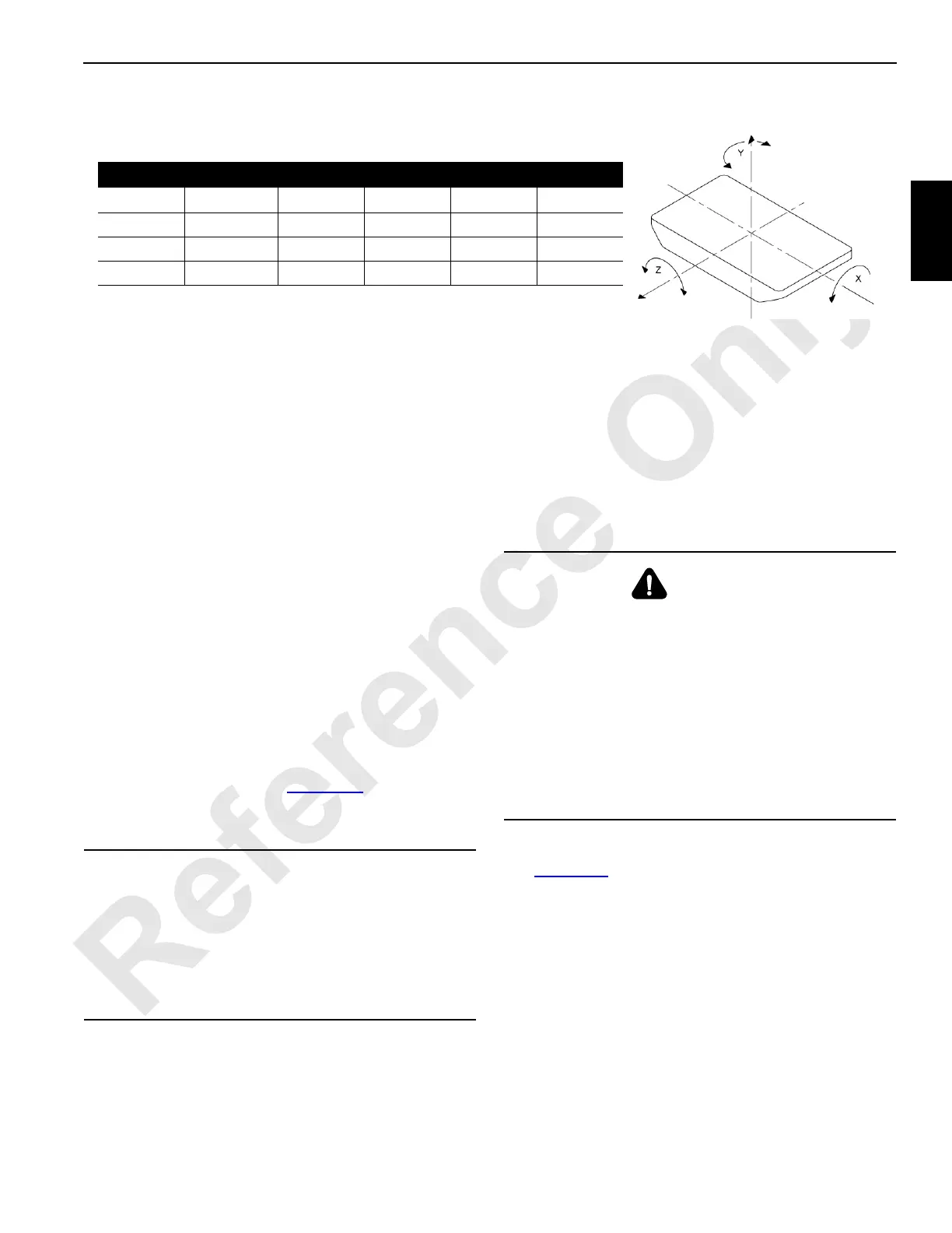
Shock loads to the crane can be experienced when the
barge is subjected to up-and-down movement of wave action
(referred to as dynamics). See Figure 2-10
for an illustration
of the dynamic conditions of the barge which will influence
the crane capacity.
NOTE: Manitowoc Cranes does not recommend crane
operation under dynamic conditions.
Operation On Barge
General
Machine list and/or dynamics will be experienced when a
crane is operated on a barge, ship, or floating platform. Both
of these conditions reduce the crane’s capacity, and each
must be taken into account for safe operation on a barge,
ship, or floating platform.
Definitions
See Figure 2-11 for the following definitions.
• A machine list, as defined by Manitowoc, is the crane’s
out-of-level (side-to-side) condition as measured by the
angle between horizontal and a line drawn through the
centerline of the crane’s boom hinge pins. This out-of-
level condition creates side load and affects the crane’s
lifting capacity.
• A barge list, (also referred to as heel or trim) causes
swingout of the load and may produce side load. When
Manitowoc Cranes provides a capacity chart showing
capacities for a 2-degree machine list, for example, we
are referring to the maximum allowable lifting capacity
for the crane when experiencing an out-of-level (side-to-
FIGURE 2-10
AXIS TRANSITIONAL ROTATIONAL
Symbol
Name Static Dynamic Static Dynamic
X Longitudinal Surge Heel List Roll
Y Vertical Heave Yaw
Z Lateral Sway Trim Pitch
CAUTION
Avoid Structural Damage!
If the crane boom or structure is shock loaded during
operation or if there is any indication of shock loading, all
structural components of the crane must be inspected to
detect cracks and other damage. Nondestructive test
equipment, such as magnetic particle or ultrasonic
procedures, is recommended for this inspection.
WARNING
Tipping Crane Hazard!
Tie-downs that only prevent the crane from shifting, as in
barge, ship, or floating platform mounting, may not
provide adequate support when using a Capacity Chart
for pedestal mounting. Before operating a crane on a
barge, ship, or floating platform, the crane user shall verify
that the correct capacity chart is being used—pedestal-
mounted, barge-mounted, the appropriate degrees list or
dynamic capacity chart.
Failing to use the correct capacity chart can result in an
accident.