Manitowoc Published 06-24-16, Control # 241-01 3-71
2250 OPERATOR MANUAL OPERATING CONTROLS AND PROCEDURES
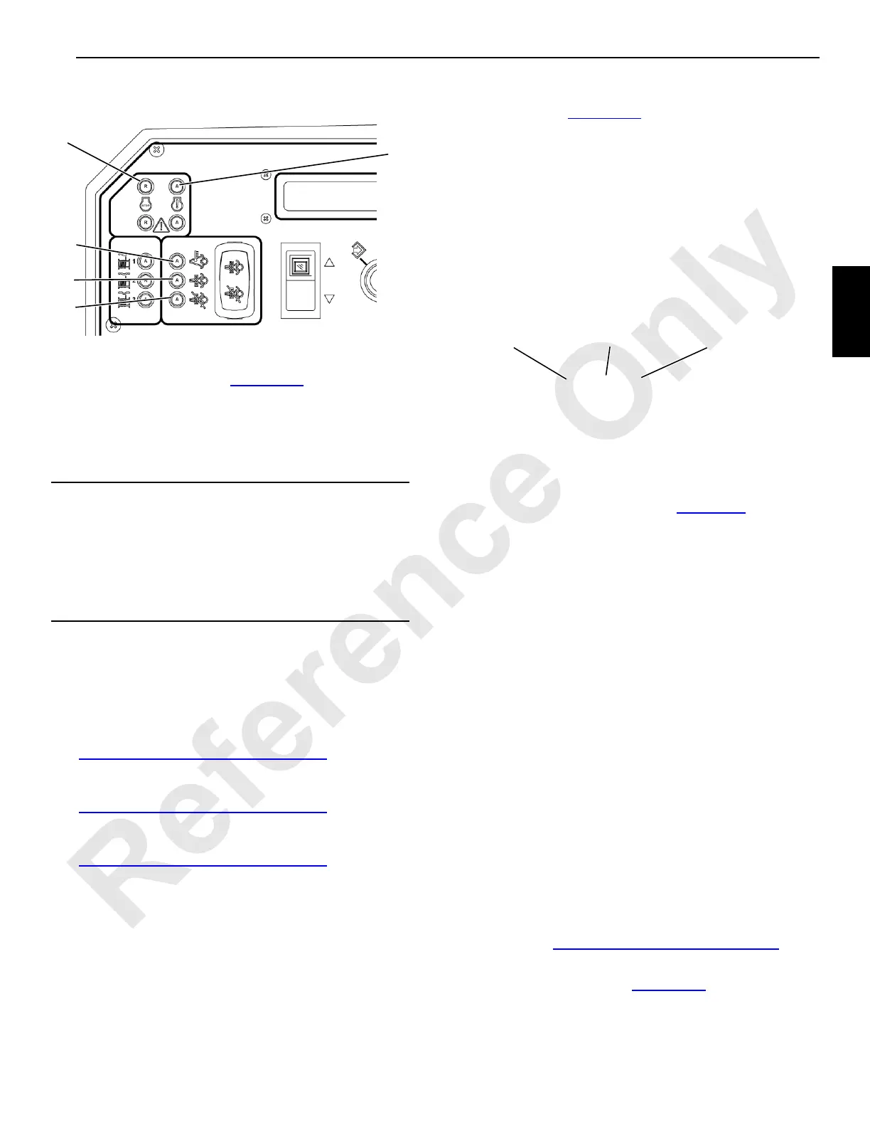
Diagnostic Lights
The engine diagnostic lights are mounted on the front
console in the operator’s cab (Figure 3-54
).
1—Engine Stop Light
The red Engine Stop light indicates the need to stop the
engine as soon as safely possible and correct the fault.
2—Engine Warning Light
The amber Engine Warning light indicates that the engine
can be run but the fault should be corrected as soon as
possible.
3—High Exhaust System Temperature
See A4—Exhaust System Lights on page 3-14 for details.
4—DPF Regeneration Active
See A4—Exhaust System Lights on page 3-14 for details.
5—DPF Regeneration Inhibited
See A4—Exhaust System Lights on page 3-14 for details.
Engine Diagnostics
The engine has two diagnostic modes, as follows:
• Off-board diagnostics—This mode requires special
hardware and software from the engine manufacturer.
• On-board diagnostics—This mode has warning lights to
alert the operator to engine problems during operation
(engine running) and has fault codes to identify specific
engine problems (Figure 3-54
).
To identify active faults, proceed as follows:
1. Stop the engine.
2. Move the ignition switch to the RUN position.
3. Move the hand throttle from LOW speed to HIGH speed
and back to LOW speed three times within five seconds.
If no active faults exist, the amber Engine Warning light
and red Engine Stop light come on but do not flash.
If there is an active fault, the amber Engine Warning light
flashes to indicate that a fault code will be flashed.
4. After another two-second pause, the red diagnostic light
flashes the fault code.
After a two-second pause, the same fault code flashes a
second time before advancing to the next fault code.
NOTE: To decipher the fault code, see Figure 3-55
.
5. See the engine manufacturer’s manual for a list of fault
codes.
DRUM INTERLOCK
General
The drum interlock physically connects both load drums on a
split drum shaft to allow single load line operation with dual
brakes either in the Free Fall or the Full Power mode.
With drum interlock, both drums are controlled by one load
drum control handle and one drum working brake pedal.
NOTE: Drum interlock cannot be used on three-drum
cranes.
Free Fall Mode
Dual working brakes, in effect, double the braking surface,
which results in less brake heat and wear.
Use drum interlock in the Free Fall mode for a concrete
bucket and similar operations where the load is continually
lowered long distances on the drum working brake.
Drum interlock in the Free Fall mode requires installing a
drive lug between the drums and rerouting the drum working
brake air lines. See Installing Drum Interlock on page 3-72
.
For drum interlock operation in the Free Fall mode, reroute
the drum working brake air lines (Figure 3-58
).
Operate the drums in Free Fall mode as follows:
CAUTION
Engine Damage!
Permanent damage can occur if the engine is run while
the red Engine Stop light is on. Do not run the engine until
the fault is corrected. If possible, lower the lifted loads and
then stop the engine as soon as possible when the red
Engine Stop light comes on.
FIGURE 3-55
3 1 9
3 Flashes—PAUSE—1 Flash—PAUSE—9 Flashes
Fault Code =