Manitowoc Published 06-24-16, Control # 241-01 3-73
2250 OPERATOR MANUAL OPERATING CONTROLS AND PROCEDURES
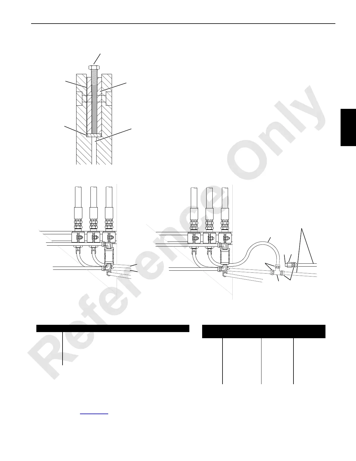
5. Remove the air fittings and reroute the air lines so they
are connected (Figure 3-58
, View A).
6. Make sure all fittings are tight to prevent air leaks.
7. Install the load line on another drum if necessary.
FIGURE 3-57
A583
1/2 inch - 13 UNC Bolt (50,8 mm [2 in])—Turn
Bolt Clockwise to Jack Drive Lug Out of Keyways
Shims
Flat Bar
9,5 mm (3/8 in) Diameter
Bar 101,60 mm (4 in) Long
Drive Lug
Drive Lug Removal
FIGURE 3-58
Air Line Identification
Air Line Identification
A Delivery Air to Right Drum Working Brake Chamber
B Delivery Air to Left Drum Working Brake Chamber
C Jumper
M1 Supply Air to Right Drum Working Brake Treadle Valve
M2 Supply Air to Left Drum Working Brake Treadle Valve
Fitting Identification for 3/8 inch O.D. Air Line
Item Description MCC
Number
Quantity
1 Tee 429629 1
2 Ferrule 429627 4
3 Nut 429628 4
4 Female
Connector
429820 1
5 Plug 571721 1
C Air Line 486056 As Required
DRUM WORKING BRAKE AIR PIPING
BA
A
B
M2
M1
BA
2
3
C
54
A
B
2
3
1
M2
M1
A586
View A
Without Drum Interlock
View B
Drum Interlock Installed with
Left Drum Brake Pedal Active
Reverse this Piping
to Make Right Drum
Brake Pedal Active