SETUP AND INSTALLATION 2250 OPERATOR MANUAL
4-36
Published 06-24-16, Control # 241-01
9. Secure all four jacks in the stored position (Figure 4-8).
10. Secure the operator’s cab in the operating position
(Figure 4-10
).
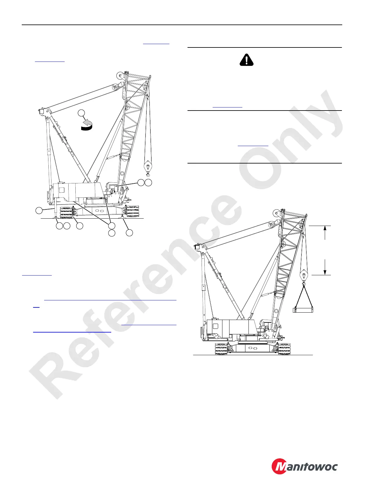
Install Counterweight and Assemble and
Attach Boom
The crane can now be used in the setup configuration. See
Figure 4-21
.
• Assemble and install the counterweights. For the
counterweight assembly and installation instructions,
see Counterweight Installation and Removal on page 4-
57.
• Assemble the boom and connect it to the boom butt. For
boom assembly instructions, see Boom Rigging Guide
(#44 HL and LR) on page 4-72.
A1048
FIGURE 4-20
5
8 10
6
7
923 4
1
DANGER
Tipping Hazard!
The crane can tip or the boom butt can collapse if the
capacity is exceeded, causing death or serious injury.
Do not exceed the maximum lifting capacity and radius
given in Figure 4-21
.
CAUTION
Avoid Boom Rigging Damage!
Avoid possible injury. Do not exceed the minimum block
distance given in Figure 4-21
. Hoisting the block higher
than specified can result in damage to the wire rope and
sheaves.
FIGURE 4-21
5,2 m (17 ft)
Minimum
A1048
View of Crane Handling
Counterweight with 27,2 t (30 USt)
Assembly Block
Maximum Capacity of 27 216 kg
(60,000 lb) at 12 m (40 ft) Radius