OPERATING CONTROLS AND PROCEDURES 2250 OPERATOR MANUAL
3-18
Published 06-24-16, Control # 241-01
C4—Digital Display
This allows the operator to monitor three groups of crane
information—operating conditions, operating limits, and
system faults. See Digital Display Readings on page 3-54
for
tables identifying the information that can be displayed.
C5—Digital Display Selector Switch
Press the top or bottom of the selector to scroll up or down
through the display readings. Release the selector when the
desired information is displayed.
C6—Operating Limit Alert
This light glows yellow, and a buzzer comes on to alert the
operator that an operating limit has been reached (the limit
automatically appears on the digital display). See Digital
Display Readings on page 3-54 for a list of operating limits,
function responses, and corrective actions.
C7—System Fault Alert
This light glows red, and a beeper comes on to alert the
operator that a system fault exists (fault automatically
appears on digital display). See Digital Display Readings on
page 3-54 for a list of system faults, causes, function
responses, and corrective actions.
C8—Rotation Indicators
These move up and down to signal the operator through
vibration that the boom hoist, luffing hoist, or corresponding
load drum is turning.
NOTE: The rotation indicators are pin-type actuators
located under the handle covers. Indicator
movement corresponds to drum speed.
C9—Wind Speed Indicator
The display shows wind speed velocity and direction at the
boom or jib point. (See the manufacturer’s instructions for
installation, operation, and maintenance instructions.)
C10—Engine Hour Meter
This shows the total number of hours the engine has been
run and is located on the front console.
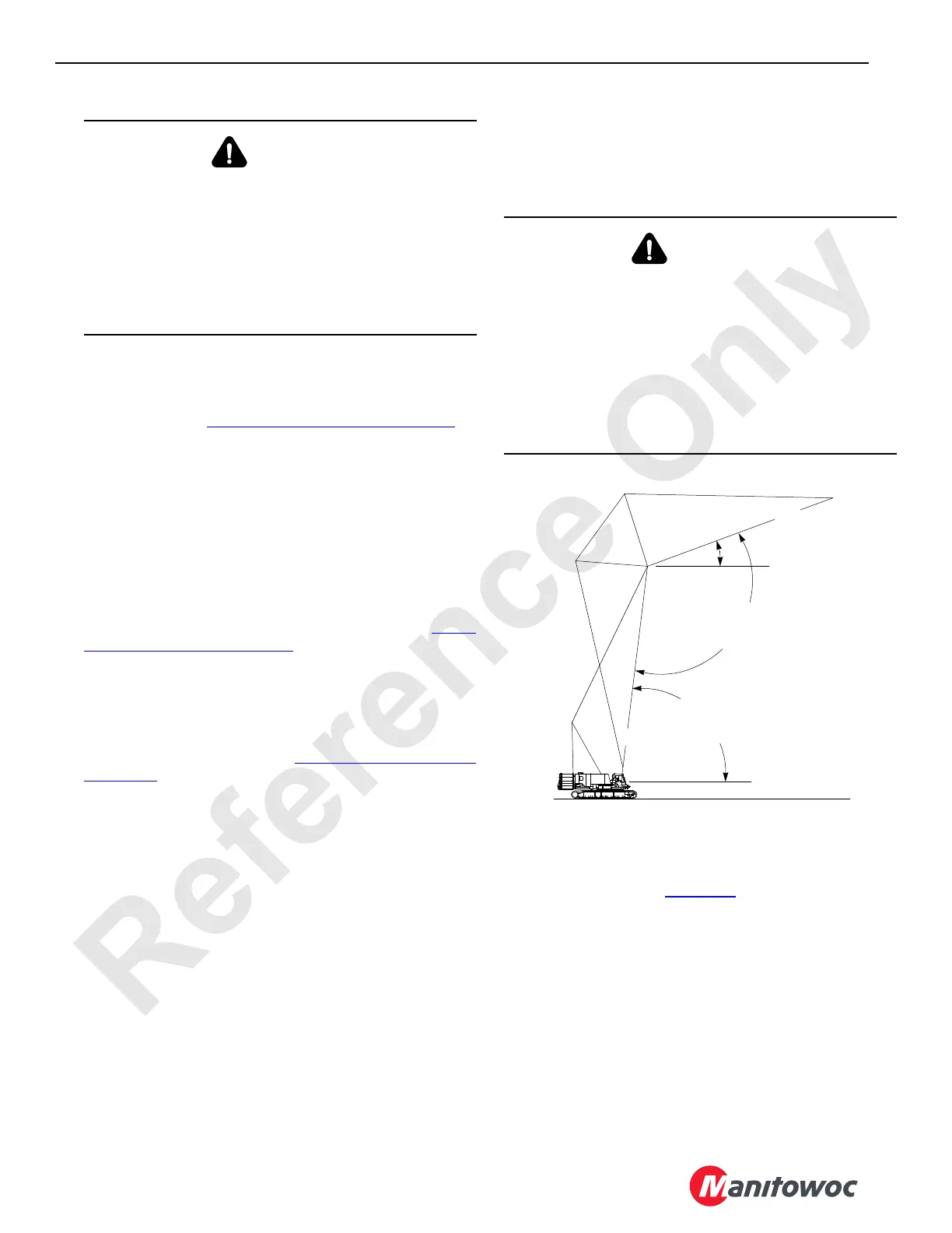
C11—Boom Angle Indicator
The boom angle indicator shows the angle of the boom in
degrees above horizontal. The boom and luffing jib angles
can also be viewed on the Operating Conditions screen of
the digital display. See Figure 3-6
for identification of the
various boom and luffing jib angles.
C12—Drum Direction Indicator
The drum direction indicator shows the direction of rotation
of the drum being used, either up or down.
WARNING
Tipping Hazard!
Avoid tipping the crane and the possibility of death or
serious injury.
Unless otherwise specified on the capacity chart, all crane
operations must be performed with the crane level to
within one percent of grade—0,31 m (1 ft) in 30,5 m
(100 ft). Operating the crane at a greater angle can cause
the crane to tip.
WARNING
Overload Hazard!
Avoid overloading the crane and the possibility of death or
serious injury.
Use the boom angle indicator only as a guide to position
the boom near the angle corresponding to the radius for a
given load.
In all cases, the radius must govern the capacity.
Exceeding the radius given in the capacity chart can result
in tipping or structural damage.
FIGURE 3-6
A528
C
L
C
L
Boom
Boom-to-Luffing
Jib Angle
Boom
Angle
Horizontal
Horizontal
Luffing Jib
Luffing Jib
Angle