OPERATING CONTROLS AND INDICATORS TMS9000-2 OPERATOR MANUAL
3-102 Published 02-21-2019, Control # 611-05
The right control lever will be used for boom lift/lower and
luffing boom extension raise and lower.
Telescoping crane function display
Refer to (Figure 3-144).NOT ENABLED: Blue background,
orange icon (this is at first key-on without pushing any
buttons)
ENABLED: Green background, white icon (this is after the
enable button has been selected)
STAND BY: Yellow background, white icon (this is after the
function has been enable, and you get out of the seat)
STANDBY FUNCTION ACTUATED: Yellow background
flashing, white icon (this occurs when a function is presently
in standby and a joystick is actuated – before sitting back in
the seat, to prevent unwanted movement)
DISABLED: Blue background, gray icon
Telescoping semi-automation menu
NOTE: For more information about telescoping with semi-
automation refer to Telescoping with semi-
automation, page 4-60.
Open menu
To open: Select symbol (1) and confirm – menu is opened
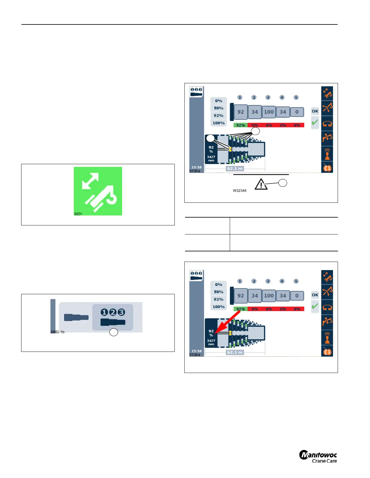
Telescope diagram display
Current relation of the telescopic sections to each other –
section of top view (Figure 3-146).
The image shown in (Figure 3-146) shows the status of the
section and cylinder pins. Green (1) indicates that the pin is
locked, Yellow (2) shows that it is in an intermediate position
and Red is unlocked. Additionally, if the hazard triangle (3) is
present, an error exists?
Telescoping cylinder length display
Display:
Current extended length of the
telescoping cylinder (Figure 3-147)
Unit of
measurement:
Displayed depending on setting, mm
(millimeters) or ft (feet) and percent (%)

 Loading...


