OPERATING CONTROLS AND INDICATORS TMS9000-2 OPERATOR MANUAL
3-122 Published 02-21-2019, Control # 611-05
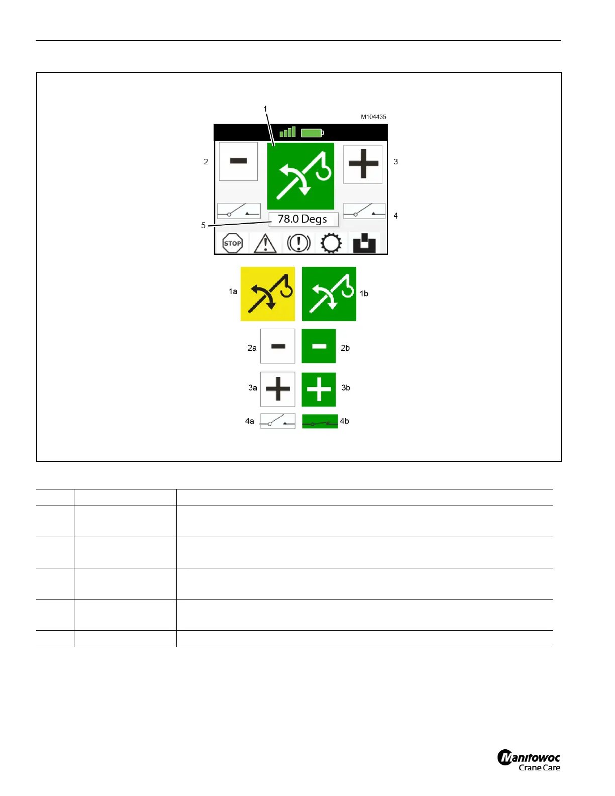
Table 3-9 Boom Lift Function Screen
Item Indicator Name Description
1 Boom Lift Function
1a - Yellow = boom cannot be operated due to a crane fault
1b - Green = boom can be operated
2 Boom Down
2a - White = boom cannot be operated until either enable button is held down
2b - Green = boom can be lowered with left motion button
3Boom Up
3a - White = boom cannot be operated until either enable button is held down
3b - Green = boom can be raised with right motion button
4 Enable Button Status
7a - White = both enable buttons released (operation disabled)
7b - Green = either enable button held down (operation enabled)
4 DEG Screen Shows the boom angle in degrees

 Loading...


