4-73
TMS9000-2 OPERATOR MANUAL OPERATING PROCEDURES
Published 02-21-2019, Control # 611-05
• Verify that the telescoping function is enabled. This is
confirmed by the green background for the icon for the
telescoping function in the right margin area of the
operating display. Refer to Figure 4-142.
• Using the operating display, enter the values for the
requested final boom configuration (such as 100-100-0-
0-0).
• Using the operating display, the Enter button is used for
the OK shown on the screen. This sends the requested
data to the control system. If this configuration is
considered acceptable, a check-mark will be shown
below the OK (as is seen in Figure 4-140). If the
configuration is not considered acceptable, a red X will
be shown instead of the check-mark. As an example, a
requested final boom configuration of 0-50-0-50-0 is not
allowed (the T3 section was “skipped” for having a non-
0% pinning location).
• Depending on the current location of the telescoping
cylinder, the cylinder may need to move to a different
boom section. If this is needed, the automated motions
will immediately occur.
• Once the telescoping cylinder is considered locked to
the boom section that is to be first moved (T2 in the
current example) by the control system, the boom
section will be unlocked (this is an automated action).
• Once the boom section is unlocked, the telescoping
direction arrows, as shown in Figure 4-140, will appear.
• With the arrows present, the operator can telescope the
first boom section to be moved (T2 in this example).
• The operator uses the joystick (or other control device)
to extend the boom section. The boom motion will slow
down near the 100% pinning location (for this example).
It can continue to be extended by the operator until it
arrives at its 100% pinning location. At this point, the
motion will be stopped and the right arrow will be
blinking. If the joystick is used in the extend direction for
at least 1 second after the arrow is blinking, then the
boom section will be locked at this pinning location. If the
joystick is not used in this time interval, then the boom
section can remain at that location and not locked (note
that the boom section could also now be retracted and
the boom fully retracted, if desired, without changing the
target tele picture / requested final boom configuration).
• Assuming that the boom section is requested to be
locked, it is important to know that there are a few
phases to the automated motion to lock the boom
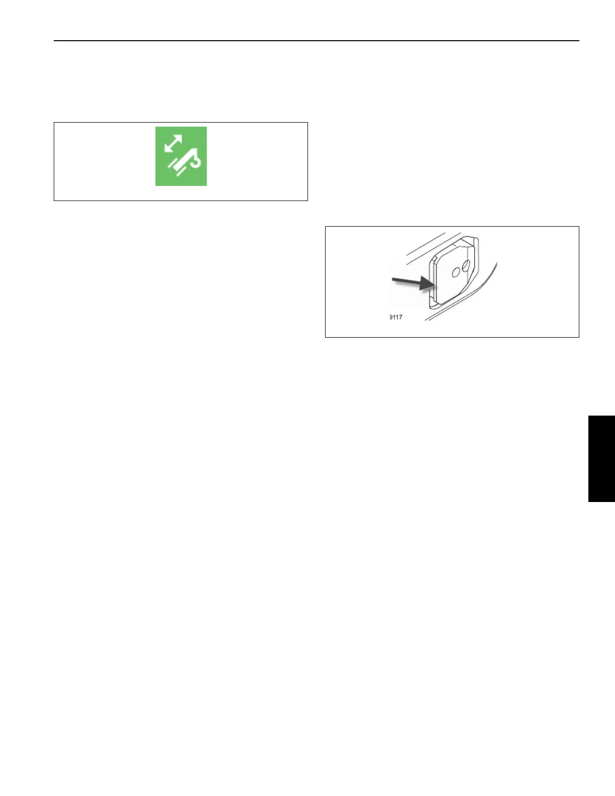
section. In particular, Figure 4-143 shows that there is a
“lip” on the boom section pins (pointed to by the arrow in
figure). The first phase for boom section locking is to
release/extend the pins into the hole/cutout in the
encompassing boom section. If this is successful, then
there is a second phase of automated motion to set
down the boom section on the proper flat surface of the
pins that is next to the lip. In a final phase, the pin is
confirmed to be engaged and the boom section locked
by the control system command the telescoping cylinder
to retract and then checking for no boom motion. If there
is no motion, then it is confirmed as locked.
• After the boom section is locked, the left AND right
arrows are shown blinking. This indicates to the operator
that the boom can be retracted or extended, and that in
either case, there will be automated motions and to be
aware that it will take some time (the blinking is an
indication to the operator that this time will be needed).
• Assuming the boom is to continue to be extended, the
operator would use the joystick (or other control device)
in the extend direction for at least 1 second. This is
interpreted as the indication to change to extending the
next boom section (T1 in this example). Therefore, the
telescoping cylinder will automatically unlock from the
T2 boom section, retract to the T1 boom section, lock to
the T1 boom section, and then unlock the T1 boom
section.
• When the T1 boom section is unlocked, the left and right
telescoping direction arrows will appear again (as is
shown in Figure 4-140).
• The operator can telescope the next boom section (T1).
• The T1 boom section operating process is the same as
for the T2 boom section described above. When the T1
boom section is at its 100% pinning location, then it can
be locked in the same manner (using the extend
direction of the joystick for at least 1 second when the
right arrow is blinking).
• With the T1 boom section at its requested final location,
only the left arrow would be blinking. This is indicating
that it is impossible to telescope the boom any further
(the boom has arrived at its final configuration as
requested).
 Loading...


