4-75
TMS9000-2 OPERATOR MANUAL OPERATING PROCEDURES
Published 02-21-2019, Control # 611-05
section to move for the new final boom configuration of 0-0-
0-100-100).
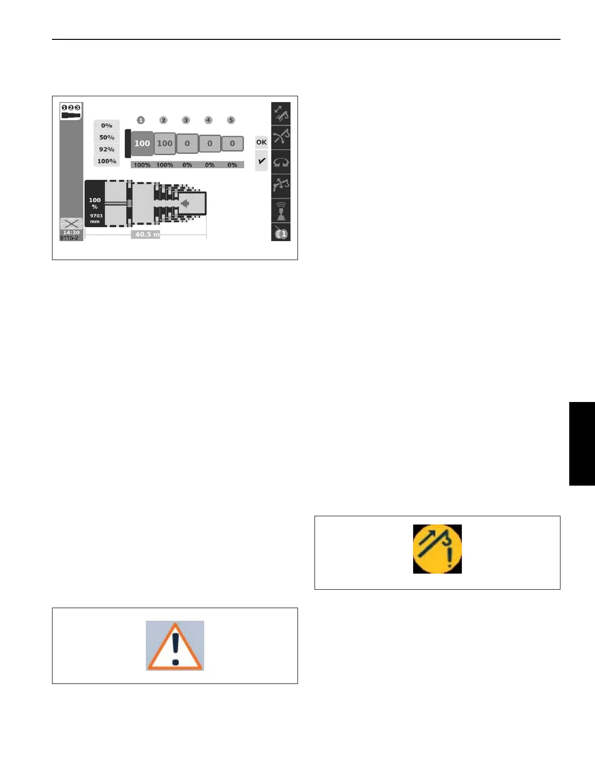
Semi-auto Mode screen refresh
When the Semi-auto screen of the operating display is
entered, the final boom configuration (“target tele picture”)
that is shown is the one most recently ACCEPTED and is
actually being used to control/operate the boom. If the
screen is exited and re-entered, what is shown may not be
the most recently REQUESTED final boom configuration.
As noted in the section of the document 'Semi-auto Mode
requiring boom to be retracted', there are cases where a
newly requested final boom configuration can not be
accepted until the current boom configuration is completed
to have the boom fully retracted. If the Semi-auto Mode is
currently requiring the boom to be retracted, and the ESC is
used to leave the Semi-auto screen, and then Semi-auto
screen is entered again, the values shown for boom sections
will revert to the original boom configuration, the ACCEPTED
boom configuration (until the boom is fully retracted and the
control system can then “shift” to the new REQUESTED final
boom configuration).
Semi-auto Mode warning indications
The control system manages a fault indication system. This
is characterized by a set of error codes or fault codes. When
a fault condition is noted by the control system, the icon in
Figure 4-145 is seen (at least in the left margin of the
operating display). There is also a screen of the operating
display that uses this icon, and that screen will show the fault
codes.
For the pinned boom control (such as in Semi-auto Mode), a
fault may be noted that is momentary. For instance, there is a
calculation of the difference between the calculated boom
length (based on the calculated boom section positions in
the control system) and the measured boom length (from the
boom outer cable reel sensor). If this difference is too large,
there is a fault condition. However, if the cable on the outer
cable reel sensor is just moved momentarily by something
near the boom, the cable may suddenly move and then
return to the proper tension. In this case, the fault condition
can appear momentarily. The icon in Figure 4-145 will
appear, and this fault code could be viewed on the operating
display, but it does not cause the telescoping function to
shut-down, and the fault code can be cleared.
For the proximity switches that sense the position of the
telescoping cylinder components and pinning mechanism,
similar momentary conditions may appear. There may also
be fault codes that appear when automated motions take
longer than expected, but the control system automatically
recovers from the condition.
For these momentary and warning conditions, the
telescoping function will continue to be available. If the left
and/or right arrows appear, then the boom can be moved in
the directions indicated by the arrows. The momentary or
warning conditions might also be helpful in diagnosing faults
that eventually cause the telescoping function to shut-down
(refer to the section in the document 'Semi-auto Mode
telescoping function shut-down'.
There are sensors in the telescoping cylinder that detect
elevated pressure conditions for extending the boom
(particularly for telescoping with significant hook loads). If the
pressure is beyond a threshold (depending on the distance
the telescoping cylinder has been extended), then the
extend motion is slowed down. If the pressure approaches
another threshold, then the extend motion is stopped. When
these conditions are apparent, the icon shown in
Figure 4-146 will be shown in the left margin of the operating
display (ODM).
Semi-auto Mode telescoping function shut-down
If the control system detects a fault that is not momentary
and not a warning indication, then the telescoping function
will be shut-down. In this case, the error icon (as seen in
Figure 4-147) will appear in the graphical schematic for the
boom (instead of the dots or the direction arrows described
previously).
 Loading...


