OPERATING PROCEDURES TMS9000-2 OPERATOR MANUAL
4-76
Published 02-21-2019, Control # 611-05
Typically shut-down condition indicates a failure in the
components of the control system (such as sensors or
modules or communications). If the only indication of faults is
for the telescoping function, then the following steps can be
used:
Cycle the power for the control system. When the power is
restored, the control system will attempt to repeat the same
procedure or automated motion that was interrupted by the
fault condition. If the fault condition was not permanent, this
may correct the condition, and if the error icon does not
appear again, then the telescoping function can continue to
be used.
If cycling the power for the control system is not effective,
and there is a load on the hook while the control system is
attempting an automated action or motion (such as
unlocking the telescoping cylinder or a boom section), then
lower the load, if possible. Without the load on the hook,
cycle the power again to attempt the automated action or
motion.
If the telescoping function is still not operable, then the
manual telescoping mode can be attempted. In this mode, it
is possible to command slight telescoping cylinder motions
to assist with locking or unlocking.
If telescoping function is still not operable, then the fault can
be assumed to be in the control system components, and
control system diagnostic procedures should be utilized.
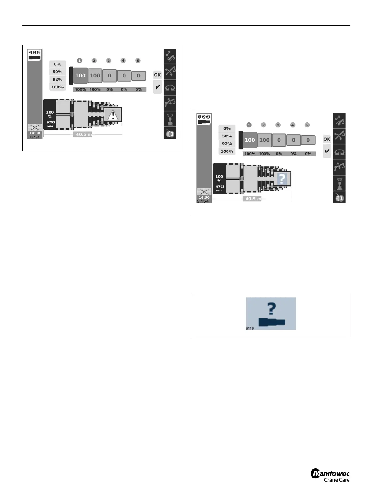
Semi-auto Mode lost boom configuration
The Semi-auto Mode is expected to continuously monitor
and record the positions of the telescoping boom sections. If
this process is interrupted, perhaps by communication
interruption or repairing a component in the control system,
then this recorded boom configuration (or “tele picture”) may
be lost. The control system will not find components in the
expected position. When this occurs, a question mark icon
will appear in the screen as shown in Figure 4-148.
The operator can attempt to correct this condition by the
procedure in section 'Reset telescoping configuration' of this
document.
Reset telescoping configuration
If the actual boom configuration (or “actual tele picture”) is no
longer considered valid by the control system (the question
mark icon appears in the Semi-auto screen), then the
following procedure can be used to reset (or “teach”) the
telescoping configuration:
• Enter the request reset telescoping screen.
Figure 4-149 shows the icon for this screen.
• The request reset telescoping screen appears as shown
in Figure 4-150. This screen is for entering a
confirmation code. The confirmation code is L-O-S-T.
When these letters are entered on the screen, then an
Enter button can be used on the OK shown on the
screen. If this is the correct code, then the reset
telescoping screen appears as shown in Figure 4-151.
 Loading...


