OPERATING PROCEDURES TMS9000-2 OPERATOR MANUAL
4-82
Published 02-21-2019, Control # 611-05
You can limit the maximum swing speed (1, Figure 4-223),
refer to Limiting the power unit speeds, page 4-85.
.
You can regulate the speed by moving the control lever or
changing the engine speed.
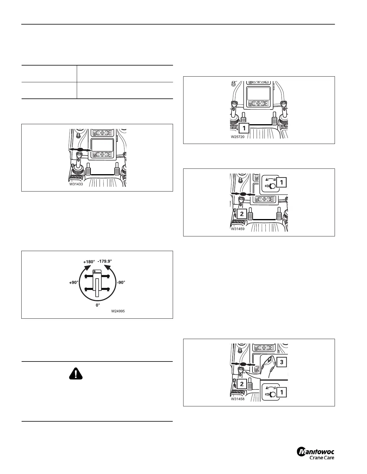
0° means that the superstructure is slewed to the, boom over
the rear (Figure 4-165).
- Angles in the left semi-circle are displayed as
positive values (0° to +180.0°).
- Angles in the right semicircle will be shown as
negative (0° to -179.9°).
Braking the swing movement
You may only brake the swing movement with the swing gear
brake.
• Depress the brake pedal (1, Figure 4-166). Do not brake
to such a degree that the load starts swinging.
If you only move the control lever to initial position, the swing
movement will slowly run down.
At the initial position, the swing movement will be stopped. At
the same time the swing gear hydraulic brake will be applied.
Free swing mode
In free swing mode, the swing brake and swing drive are
released and the crane can swing freely when external
forces act upon the load or boom. To activate free swing
mode:
• Switch on the swing gear.
The swing gear brake is released – lamp (1,
Figure 4-168) lights up.
• Shift the control lever (2) to its initial position.
• Press the button (3).
The swing gear hydraulic brake is released.
• When the free swing mode is active, the icon shown in
Figure 4-169 (swing function icon with yellow border) will
To swing to the left:
• Push the control lever to the left
(Figure 4-164).
To swing to the
right:
• Push the control lever to the
right.
WARNING
Boom Damage Hazard!
Switching off the swing drive will activate the swing brake
immediately. If the crane is swinging, abrupt stopping will
create a shock load that could result in damage or
buckling of the boom. Death or Serious injury may occur.
 Loading...


