EasyManuals Logo
Home>Manitowoc>Construction Equipment>Grove TMS9000-2 Series

Manitowoc Grove TMS9000-2 Series User Manual

Manitowoc Grove TMS9000-2 Series
430 pages
To Next Page IconTo Next Page
To Previous Page IconTo Previous Page
Page #382 background imageLoading...
Page #382 background image
SET-UP AND INSTALLATION TMS9000-2 OPERATOR MANUAL
6-46
Published 02-21-2019, Control # 611-05
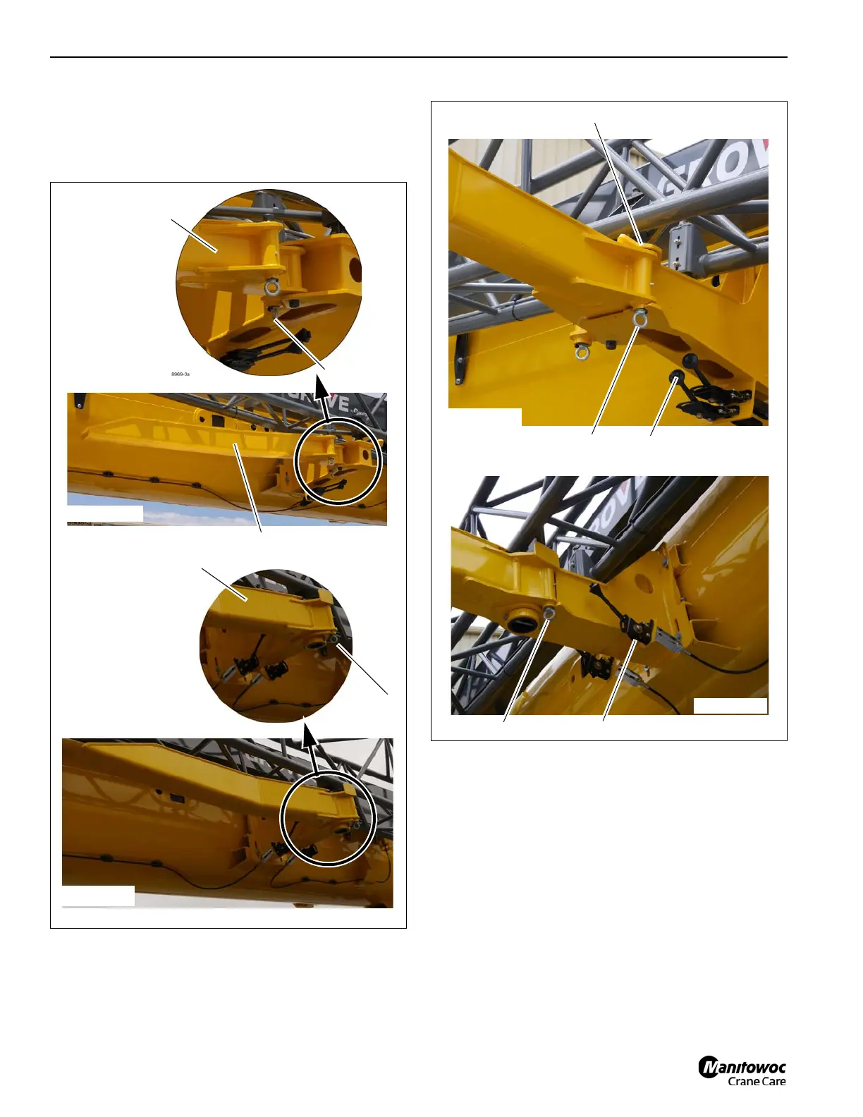
5. Verify that the Design A horizontal actuated hand levers
(3, Figure 6-77) are pushed fully towards the front of the
main boom. Verify that the Design B vertical actuated
hand levers are pushed fully upwards. This engages the
two pins securing the fly extension to the main boom.
6. Remove the retaining clip (1, Figure 6-78) and remove
the pin (2) from the locking bar (3) and the fly extension
FIGURE 6-76
8969-3
1
2
2
9728-2
9728-1
1
2
Design B
Design A
FIGURE 6-77
8969-4
1
2
3
Design A
9728-3
1
3
Design B

Table of Contents

Questions and Answers:

Question and Answer IconNeed help?

Do you have a question about the Manitowoc Grove TMS9000-2 Series and is the answer not in the manual?

Manitowoc Grove TMS9000-2 Series Specifications

General IconGeneral
BrandManitowoc
ModelGrove TMS9000-2 Series
CategoryConstruction Equipment
LanguageEnglish

Related product manuals