GROVE 6-47
TMS9000-2 OPERATOR MANUAL SET-UP AND INSTALLATION
Published 02-21-2019, Control # 611-05
(4). Insert the pin in the locking bar and secure with the
retaining clip.
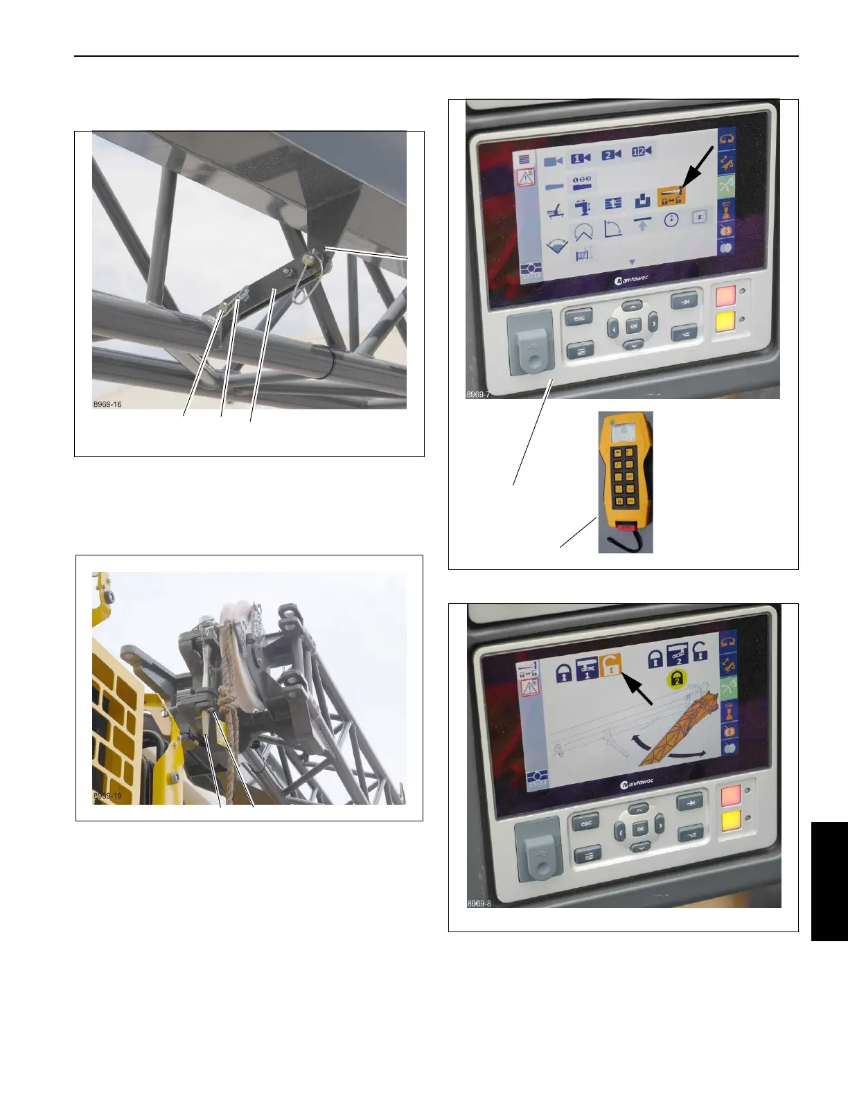
7. Remove the retaining clip (1, Figure 6-79) from the pin
(2) installed in the fly extension attachment fittings and
the base extension anchor fittings. Remove the pin and
insert in stowage lugs in base extension, secure with
retaining clip.
8. In the cab on the CCS display (1) press menu and then
select the extension menu (Figure 6-80). To use the
hand-held remote controller (2) refer to Boom Extension
Assist, page 3-127.
9. Select pin #1, unlock (Figure 6-81).
10. The icons turn green, verifying pin #1 is unlocked
(Figure 6-82).
FIGURE 6-80
8969-7
9728-6
1
2
 Loading...


