GROVE 6-49
TMS9000-2 OPERATOR MANUAL SET-UP AND INSTALLATION
Published 02-21-2019, Control # 611-05
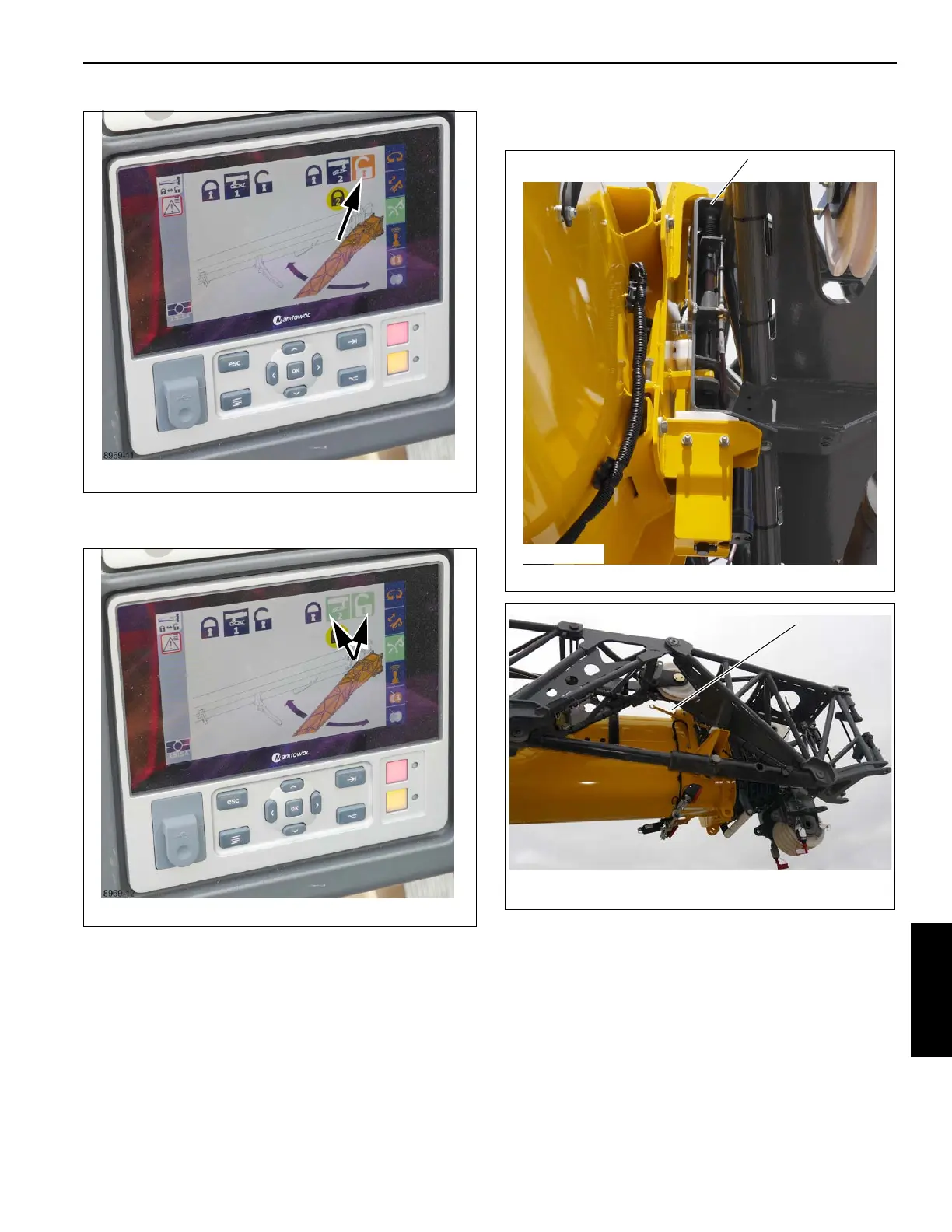
15. The icons turn green, verifying pin #2 is unlocked
(Figure 6-87).
16. Verify pin #2 is unlocked (1, Figure 6-88). The handle (1,
Figure 6-89) will be in the down position.
NOTE: Pin #2 will not unlock unless the right side boom
nose pins are fully engaged. If Pin #2 does not
unlock make sure the right side boom nose pins
are fully engaged and the cable ends are inserted
through the pins, refer to (4, Figure 6-85).
17. Swing the extension around to engage the left extension
anchor fittings (1, Figure 6-90) with the left main boom
attachment fittings (2). Insert the pins (3) through the
fittings using an impact driver turning the jack screw
counterclockwise. The jack screw drive bolt will bottom
out when the pins are fully engaged.
FIGURE 6-88
8969-13
1
Design A
 Loading...


