GROVE 6-67
TMS9000-2 OPERATOR MANUAL SET-UP AND INSTALLATION
Published 02-21-2019, Control # 611-05
3. Using the impact driver turn the jack screw (1)
(Figure 6-129) clockwise to remove the pins (2) from the
attachment lugs (3).
4. Using the tag line swing the boom extension around until
the extension is on the run-up ramp. Note: Raise the
main boom to aid extension to fully engage the pin #2
location.
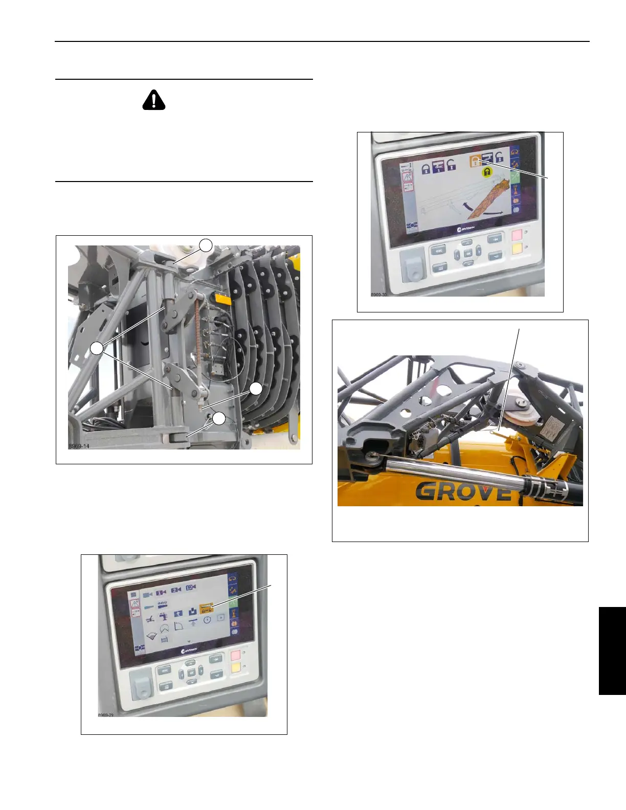
5. On the CCS screen navigate to the boom extension icon
(1) (Figure 6-130).
6. Select pin #2 lock (1) (Figure 6-131), the pin #2 icons
turn green (1) (Figure 6-134). The lever handle (1)
(Figure 6-132) should move up and the cable pins (1)
(Figure 6-133) should retract from the attachment pins
(2).
DANGER
Crushing Hazard!
Ensure the pins on the right side are properly installed and
the extension is secured from swinging around before
disconnecting the left side pins. Death or serious injury
could occur.

 Loading...


