GROVE 6-69
TMS9000-2 OPERATOR MANUAL SET-UP AND INSTALLATION
Published 02-21-2019, Control # 611-05
8. Using the impact driver turn the jack screw (1)
(Figure 6-136) clockwise until the pins (2) are fully out of
the lugs (3).
9. Raise the main boom to assist in causing the boom
extension to fully engage the run-up ramp then lower the
main boom.
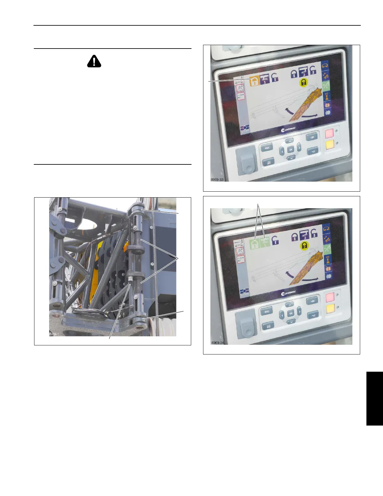
10. On the CCS screen select pin #1 lock (1) (Figure 6-137),
the pin #1 icons turn green (1) (Figure 6-141). You can
also use the hand held remote to secure pin #1, refer to
Operating Remote Control, page 3-114.
11. Actuate pin #1 before moving handles so that the
extension is fully secured before moving under it to
operate the handles.
DANGER
If pin #2 (1) (Figure 6-135) does not engage the 35 ft (10.5
m) extension, STOP. DO NOT continue to stow the boom
extensions until pin #2 has properly engaged the
extension.
DO NOT climb onto decking or walk under boom
extensions.
Severe injury or death may occur if the front latching
mechanism is not properly attached to the boom
extensions; the boom extensions may fall or swing away
from the main boom stowage brackets.
Refer to the Service Manual to align the extension with
the spring pin or the locking pin.

 Loading...


