SET-UP AND INSTALLATION TMS9000-2 OPERATOR MANUAL
6-70
Published 02-21-2019, Control # 611-05
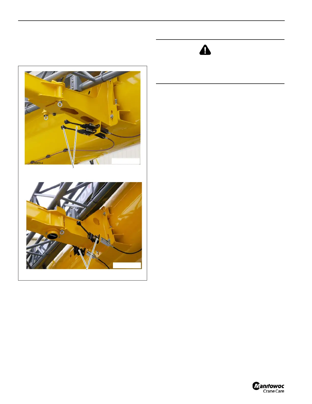
12. Push the Design A horizontal actuated hand levers (1)
(Figure 6-139) towards the front of the main boom. Push
the Design B vertical actuated hand levers fully
upwards. This disengages the pins that secure the fly
extension to the main boom (1, Figure 6-140).
FIGURE 6-139
8969-4
1
Design B
9728-9
1
Design A
DANGER
Boom Extension Hazard!
Ensure the fly extension is secured to the main boom
before removing connections to base extension. Failure
to do so could result in death or serious injury.

 Loading...


