ON-BOARD DIAGNOSTIC
STEP INSPECTION
ACTION
13
VERIFY TROUBLESHOOTING OF DTC P1504
COMPLETED
• Make sure to reconnect all disconnected
connectors.
• Clear DTC using NGS tester.
• Start engine and warm it up completely.
• Is same DTC No. present?
Yes
Replace PCM, then go to next step.
No Go to next step.
14
VERIFY AFTER REPAIR PROCEDURE
• Perform “After Repair Procedure.”
(See F1-36 AFTER REPAIR PROCEDURE)
• Are any DTCs present?
Yes
Go to applicable DTC inspection.
(See F1-37 DTC TABLE)
No
Troubleshooting completed.
DTC P1562
Except for GF4A-EL Models
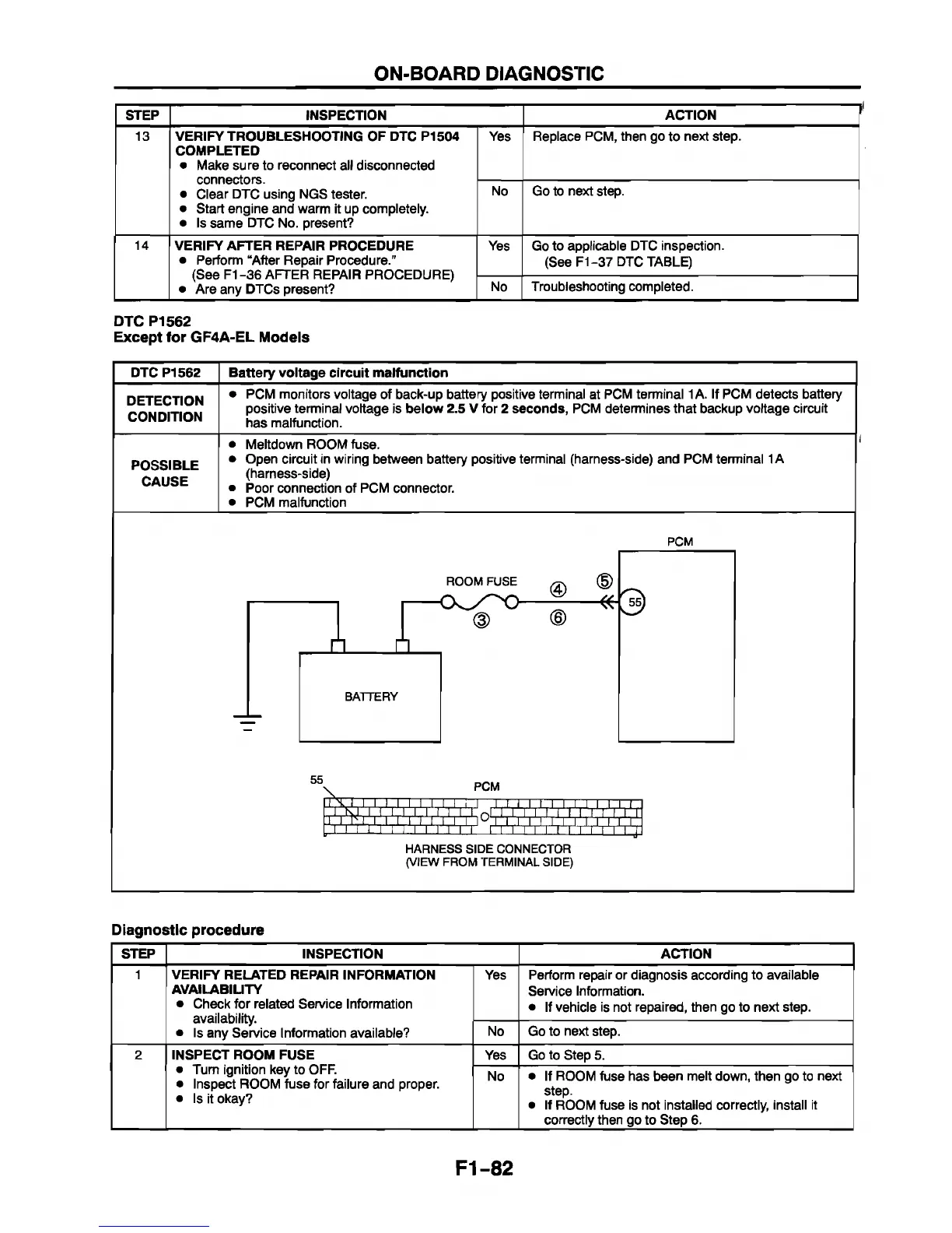
DTC P1562 Battery voltage circuit malfunction
DETECTION
CONDITION
• PCM monitors voltage of back-up battery positive terminal at PCM terminal 1 A. If PCM detects battery
positive terminal voltage is below 2.5 V for 2 seconds, PCM determines that backup voltage circuit
has malfunction.
POSSIBLE
CAUSE
Meltdown ROOM fuse.
Open circuit in wiring between battery positive terminal (harness-side) and PCM terminal 1A
(harness-side)
Poor connection of PCM connector.
PCM malfunction
PCM
ROOM FUSE
55
T T T 1
PCM
I, I , I, I, I, I, I, r
I i .i i.i.i I ix r
¡'¡'I'
........
.
r r r i i i i
x
HARNESS SIDE CONNECTOR
(VIEW FROM TERMINAL SIDE)
Diagnostic procedure
STEP
INSPECTION
ACTION
1
VERIFY RELATED REPAIR INFORMATION
AVAILABILITY
• Check for related Service Information
availability.
• Is any Service Information available?
Yes Perform repair or diagnosis according to available
Service Information.
• If vehicle is not repaired, then go to next step.
No Go to next step.
2 INSPECT ROOM FUSE
• Turn ignition key to OFF.
• Inspect ROOM fuse for failure and proper.
• Is it okay?
Yes Go to Step 5.
No
• If ROOM fuse has been melt down, then go to next
step.
• If ROOM fuse is not installed correctly, install it
correctly then go to Step 6.
F1-82


 To Next Page